Car speed and especially distance measurement is relatively easy to achieve. The simplest method is to count the revolutions of one of the cars wheels. The distance can then be determined by multiplying this value by the measured circumference of the wheel.
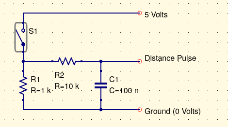
The simplest sensor to use is a wired cycle computers reed switch along with a magnet attached to a suitable wheel. When the magnet passes the switch is closes and then opens which can be used to create a voltage pulse. One issue with switches is a thing called switch bounce. This is where when a switch is opened or closed it can bounce on/off a few times which can create extra pulses. So we need to filter the input somehow either in the electronics and/or the software that receive the pulses. A typical input circuit is shown below.
The resistor R2 and C1 forms a simple low pass filter with a time constant of 1ms to reduce switch bounce. Some figures:
| Car Speed | 60 km/H |
| Wheel diameter | 0.412 m |
| Wheel circumference | 1.294 m |
| Number of pulses per second | 12.879 pulses/s |
The software has to count these pulses ideally while it is doing other work. So normally we would use an internal hardware timer or an interrupt based system to do this. With an interrupt based system the microcontroller code is running some general control code and is interrupted from this to run through a small section of code, called an interrupt routine, on each distance pulse. Different microcontroller and software languages have different ways of implementing this.
For the Picaxe running on a GpSpeed controller it can be implemented using its I2/RB4 input pin. This has a suitable electronic filter from the P2 connectors pin 1. Note the Picaxe "polled interrupts" are level sensitive, so you need to interrupt on the high level, followed by the low level etc.
; Variables assigned to Picaxe registers
symbol distance = w23 ; Note only 16bit so up to 65535 counts
symbol distanceToggle = b47 ; Distance interrupt toggle
; Software initialisation
init:
setint %00010000,%00010000,B ; initialise interrupts on port B bit 4
main:
; The the main program
; The interrupt routine
interrupt:
if distanceToggle = 0 then
distance = distance + 1
setint %00000000,%00010000,B
distanceToggle = 1
else
setint %00010000,%00010000,B
distanceToggle = 0
endif
return
See: http://www.picaxe.com/BASIC-Commands/Interrupts-and-Multi-Tasking/setint/
For a microcontroller timer based system you will need to look at how this is implemented for the microcontroller and software environment you are using. In essence each pulse would increment a hardware based counter which can be read by the software at any time. There is no software involvement in the counting itself this is all implemented in the microcontroller timer hardware. This is much better than using software interrupts if available.
To calculate the speed we need to measure the distance with respect to time. We have already measured the distance travelled using the distance measurement above. We now need to measure the time and calculate the speed. Normally a microcontroller has a hardware timer counting pulses based on its master clock oscilator. This count will thus define a time. The units of this time depends on how fast the clock being counted is. It is unlikely to be directly in seconds or a fraction of a second so some scaling of the calculation is likely to be required. The basic calculation for speed is:
speed = distance / time
TBD