Telemetry is a very useful facility to have in the Greenpower challenge. It allows the pitside crew to see some aspects of what is happening on the car, live during a race. One of the core pieces of information is the state of the batteries and their average energy usage allowing the team to manage the cars battery energy to go as far/fast as possible throughout the whole race. It also allows problems such as motor overheating etc to be diagnosed during the race such that some mitigating actions can be taken.
More that this it allows the young team engineers to do some engineering work, gathering data and diagnosing things as well as managing the cars power level during the race when otherwise they would not have anything significant to do. Unfortunately Greenpower banned the ability to manage the cars power directly over the communications link, reducing the benefit of encouraging the youngsters to do this but at least the engineering team can tell the driver to change power settings over a walkie-talkie system or the like.
Basically it allows the communication of measured cars parameters to be sent to a remote site for viewing/storage. In terms of Greenpower this will normally involve a form of wireless communications link.
Telemetry is strongly linked with providing data logging abilities as described at: DataLogging.html. The first thing you have to decide is what things to measure and transmit. The ideas for this are described in the data logging section. A simple use of telemetry is simply to transmit each data log packet that is being stored in the car over the wireless link to the pits receiver.
There are a number of wireless methods that can be used, each with there advantages and disadvantages such that no one stands out as being ideal. All wireless systems have their problems these being mainly range and line of sight operation only for some systems.
Some of these methods are line of sight only. This is not normally a serious disadvantage as long as the data you are sending includes average values for some items, such as average current for the last lap etc.
Some basic methods follow:
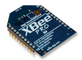
Zigbee is a low power wireless standard really design for home automation. It operates in the 2.4GHz radio band and so shares its spectrum with WiFi and Bluetooth amongst other standards. These will interfere with one another to a degree, however the system will work, line of sight, at a range of about 1.5km or more and so can work fine for Greenpower usage. It is the method that the Rotary Racer team has used for a number of years and has generally worked well. You do need to make sure you use the point-point system rather than a mesh type system to allow it to work well however. It is relatively inexpensive (about £25 per transceiver module) and uses cheap and readily available WiFi aerials and leads.
A suitable module we have used is the: Xbee: XBP24-AUI-001, http://uk.farnell.com/digi-international/xbp24-aui-001/mod-xbee-pro-802-15-4-u-fl-conn/dp/1337918 but there are many others with different aerial connection types and variations on the Zigbee protocol used.
These are more conventional telemetry style radio systems. Simple to use transceiver modules are available from many sources. as are suitable aerials and leads. These are line of sight wireless methods that can work at a range of a few hundred meters depending on the module and how good its aerial is.
One of the many mobile phone data communications standards can be used for communications using Internet IPV4/IPV6 protocols. This method requires two units with a suitable mobile phone contract/plan. The pitside unit can be a normal mobile phone, ideally linked to a laptop to make the data available for the team to easily see. Some form of static IP address for one of the units will be needed for communications or a separate server on the Internet with a static IP address can be used as a go-between.
Problems with this system can be cost of usage for low budget school teams and the lack of mobile phone signal at some of the Greenpower race circuits. It can however, if there is a good mobile phone coverage, provide data from all around the circuit.
WiFi modules are available. These normally have a restricted range and setup times to connect or reconnect when signal loss occurs can be long resulting in restricted data. However it can take the pits receiving system easier as laptops and mobile phones normally have WiFi radios built in.
Bluetooth is a very short range (< 10m) low power wireless communications system designed for short distance audio and control purposes. It won't be useful for a direct telemetry usage, but could be used for in-car communications to a mobile phone or tablet. This phone could use used for data storage and perhaps transmission of the data over the mobile phone GSM data changes to an Internet device. Bluetooth devices are available in the XBee form factor.
If you have a willing radio ham available to your team there are many amateur radio bands that can be used for communications.
The core Greenpower rules affecting the telemetry system are:
Unfortunately the last of these is quite restrictive disallowing things like pit now LED's or driver messages etc as well as managing the power levels from the pits. It is also quite difficult to prove if it is happening. We have cut the transmit data line from RF receiver module to the car electronics to prove/make sure this cannot happen. This is ok with simple serial communication modules used in a simplistic way, but would be difficult to make sure of with some communications systems.
As given above, there are quite a number of ways of implementing telemetry. This sections just describes one method that can be used with the GpSpeed controller or other systems.
In order to transmit the data the telemetry module needs to be connected to the data logging system and the data logging system needs to send the appropriate data across the link. A simple system to do this uses simple serial communications. A number of RF transceiver modules support this as well as almost all micro controllers. Also a suitable power supply is needed, typically 3.3 Volts or 5 Volts. If the system is connected to the speed controller or other car electrics in any way, this power supply has to come from the main 24 Volt car batteries due to the GP regulations.
The GpSpeed controller provides a 4-pin connector for this purpose. This connector, P3, Provides a ground pin, a 5V power supply pin, a serial transmit data pin and a serial receive data pin.
One useful type of RF modules used by many, is the XBee series. The XBee series defines a certain module format and pin-out and has many module types to handle different radio communication types including Zigbee, 433 Mhz, 868 MHz, Wifi, Bluetooth etc. They use a simple two wire serial communications scheme. We have used an XBee XBP24-AUI-001 module to good effect.
The XBee module needs 3.3 Volts of power and a suitable board to mount it on. We actually built our unit using vero board and a small 3.3V linear regulator + 2 capacitors. Note that the pin spacing on XBees is 2mm so either a 2mm pitch prototyping board is needed or the pins of a suitable 2mm connector bent and cut off to fit is needed.
There are also now breakout boards available on the market, such as this one from SparkFun that will do the job: https://www.sparkfun.com/products/11373
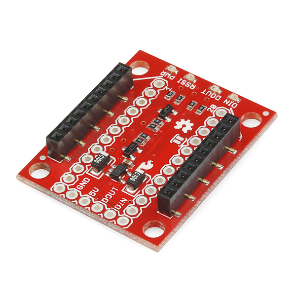
With just the 4 appropriate wires connected to the GpSpeed, a suitable XBee module installed with aerial you have the car side of the telemetry electronics.
For the pitside transceiver the same type of XBee transceiver module can be used, but a more laptop friendly, USB type of connection is useful so the module can be directly connected to and powered from the laptop. Again Sparkfun make such a suitable breakout board the: https://www.sparkfun.com/products/11812
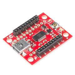
You can obviously roll your own breakout boards as wanted.
Some software is needed both at the car end and at the pitside Laptop, tablet or phone to receive the data and display it in a suitable form. This same software can be used to view the data logs post race if the telemetry data packets and data log packets are the same.
Normally the way these wireless transceiver modules work is that they are "transparent" to the serial communications. That is a byte of data sent from the GP car's electronics into the transceivers serial port will appear at the remote transceivers serial port and visa versa. This allows the electronics and software to essentially ignore the fact that there are wireless transceivers in the path of the serial communications.
The cars electronics will then send "packets" of data every so often over this serial interface. Normally a packet of data will be a set of values for a particular time. For example Rotary Racer sends a packet of data once per second with all of the logged parameters. This includes time, voltage, current, average lap current, speed, distance, GPS position etc. This packet of data can be in computer binary form or in human readable ASCII character form. Computer binary form is much easier and more efficient for computers to process, but human readable ASCII is easier for humans to see what is going on and debug the system.
A simple ASCII based system would send one line of comma separated ASCII numeric values terminated with the "NewLine" (0x0A) character.
However to get this to work there is often some configuration of the transceiver modules needed to implement a point to point link. This maybe setting up the channel frequency to use or the nodes address.
See the section on software for more info.
The XBee modules need to be setup so that they can form a transparent communications link. In order to do this you need to be able to send them configuration commands over the serial link. If you are using a USB board for the XBee's you can program them one at a time from a PC the XBee is connected to. A simple serial terminal program can be used for this.
The XBee has a command mode available that accepts "AT" commands. To get to this command mode you need to:
Each XBee has a unique address. You configure each XBee with the other units address as the destination of where to send its packets. You also configure the radio frequency channel to use. The modules address is split into high and low fields as it is quite a long address. First find both modes addresses. To find out a modules address use the ATSH and ATSL commands. This will display those values. Write them down somewhere secure (Computer information file ?). Then program the cars and pitside's modules as follows.
| Car side command | Description |
|---|---|
| ATNICarName | Sets ID string |
| ATDHxxxxxx | Sets destination high address (pit side) |
| ATDLxxxxxx | Sets destination low address (pit side) |
| ATCH0C | Sets the channel in HEX |
| ATWR | Write to non volatile memory |
| Pit side command | Description |
|---|---|
| ATNIPitName | Sets ID string |
| ATDHxxxxxx | Sets destination high address (car side) |
| ATDLxxxxxx | Sets destination low address (car side) |
| ATCH0C | Sets the channel in HEX |
| ATWR | Write to non volatile memory |
Once this has been done any serial data received on one modules serial port will be sent out of the others serial port and visa versa.
There is more information on the commands available in the modules data sheets or application notes. Some interesting other AT commands are:
| Command | Description |
|---|---|
| <1sec>+++<1sec> | Enter command mode |
| ATCN | Exit command mode |
| ATDB | Signal strength (0x24 - 0x64) in -dB |
| ATSH | Display nodes high address |
| ATSL | Display nodes low address |
| ATIDxxxx | Set Personal Area Network ID |
| ATDHxxxx | Set destination address High |
| ATDLxxxx | Set destination address Low |
| ATMY | Sets my 16bit address |
| ATCH | Read channel |
| ATCH12 | Set channel in hex (0x0C - 0x17) |
| ATND | Discover nodes |
| ATPL | Get power level (4 is full power) |
| ATPL4 | Set power level 4 |
| ATCA | Check transmit power threshold |
| ATCA00 | Set threshold off |