One of the core things to get right in a Greenpower race is to manage the average energy consumption of your car so that you just about use up all of the energy in the batteries. In order to do this we need to measure some things. The core electrical measurements will be the batteries voltage and the current being taken from the batteries.
There are two sides to this. First you need to know how much energy your batteries actually have and second you need to measure the average energy taken from the batteries during the race.
The amount of energy contained within the batteries is relatively difficult to determine. It depends on the type of battery, its condition, how well charged it is, the temperature etc. However we can perform tests and measurements to get a usefully accurate figure. The core measurements to do this are voltage, current and temperature.
The voltage across the battery terminals is an indicator of their level of charge. But it is only an indicator and is subject to wild variations based on the current flowing, the batteries condition and the temperature of the batteries amongst other things.
Keeping a tally of the average current being drawn from the battery allows us to determine how much energy has been used and thus (if we know how much energy the batteries contain) how much is left. This is a good measurement to manage the cars power during a race, but does need a good knowledge of your batteries condition and energy content.
For information on batteries and testing them see the Batteries and the TestRigs.html information.
Measuring voltage is relatively eay. There are many ways to do this. These include:
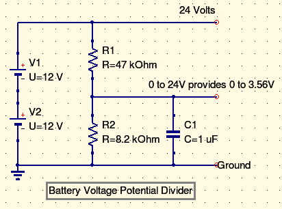
Commonly a small Micro-controller device such as a PIC processor, an Atmel device as used in Ardinos or an ARM based chip will be used to perform measurements. These devices have an analogue to digital convertor in them that allows the conversion of a voltage into a digital number. Greenpower uses two 12 Volt batteries connected in series to produce 24 Volts. It is likely any electronics device will only allow a 0 - 5V range to be input (pr peehaps 0 - 3.3V) and so the 0 - 24V range of the batteries has to be reduced using a simple resistive potential divider.
This circuit has a capacitor across its output. This is to filter out noise on the voltages measurement so the final reading is more stable.
There are two main ways of measuring a current. One is to place a small valued resistor in series with the current flow and measure the voltage drop across it caused by the resistance to the flow of current (I = V / V (Ohms Law)). This can be problematic for the battery current in Greenpower. The motor can, in a stalled starting from the grid condition, take over 130 Amps which is a lot of current. In order to measure this level of current a very small resistor value is needed, perhaps 0.0001 ohms, otherwise the resistor will heat up enormously and loose lots of battery energy even if it doesn't blow up. Also the amount of measured voltage is likely to be low (perhaps 0 - 0.013 Volts. This would need amplification before using a micro processors ADC to measure it. However this method is possible.
A more useful and efficient method is to use a Hall Effect device. This measures the current by measuring the magnetic field produced by the current flow. They are available to mount on a PCB and take the current through their pins or have a hole to allow the wire carrying the current to be passed through. Some, like the one on the GpSpeed controller, have in-built amplification and signal conditioning to provide a simple variable voltage proportional to the current flow.
Its not often good enough to be able to measure just the instantaneous current flowing into the motor. As a Greenpower car travels around a track the current used can vary wildly due to wind and hills as well as slowing down and speeding up. (See rotary racers data logging data at: http://www.greenpower.beamweb.co.uk/files/RotaryRacer/performance). The current can vary from 8 Amps to over 40 Amps in a single lap as the car goes into/down wind and/or up/down hills. So it can be very difficult for a driver or the pitside engineer via telemetry data to determine what overal current is being taken from the batteries.
Ideally what we need is some form of averaged current reading. The question is over what period to average over. Some ideas:
This is probably the easiest way to implement current averaging. To implement this the cars electronics need a method of measuring distance. This is normally performed by counting the pulses from a cycle computer type reed magnetic switch. The measured instantainious current is then summed into a total register counting how many have been added. Once the lap distance has been covered the total register is divided by the number added to yield the average current per lap. So we have the following processes happening (in rough 'C' programiing language code):
Init
distance = 0;
distanceLap = 2300; // The number of wheel rotations per lap
avgCurrent = 0;;
avgCurrentNumber = 0;
avgCurrentLap = 0;
On wheel relay pulse:
distance = distance + 1;
Once per second (or perhaps 10 seconds)
current = measureCurrent(); // Measure the current
avgCurrent = avgCurrent + current; // Sum the currents
avgCurrentNumber = avgCurrentNumber + 1;
if(distance >= distanceLap){
avgCurrentLap = avgCurrent / avgCurrentNumber;
avgCurrentLap = 0;
avgCurrentNumber = 0;
distance = 0;
}
Note that some of these variables will need to store quite large numbers. The distance and average toral registers will probably need to be 32bit. So when using smaller 8 or 16 bit micocrontrollers using some programming languages, more work has to be done to implement these 32bit storage registers (Picaxe).