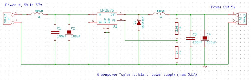
To power low energy circuits from the main 24V batteries with transient voltage spike protection. This circuit uses a simple, and easily solderable, switch mode regulator chip available in a through hole TO-220 package or surface mount DPAK package to provide an efficientish (77%) 5V or other voltage supply in the range 1.23V to 37V at up to 0.5Amps.
The input power from a 5V to 37V battery source is passed through an inductor (L1) and onto some capacitors (C1,C2) to reduce the level of spikes that can occur on the normal 24V DC supply due to on/off motor switching. The regulator chip switches this on/off through inductor L2 into the final voltage smoothing capacitors (C3,C4). The resistors R1, R2 set the voltage feedback for voltage level control. These can be changed to advust the output voltage of the circuit from about 1.23V to 37V (has to be less than input voltage). Seet the data sheet for the LM2575 for information. The diode D1, is the flyback diode to keep the current flowing when the switched mode regulators output is switched off.
To set the required output voltage:
With R2 = 1k
R1 = R2(Vout/1.23 - 1)
To come, but veroboard will do.
Design files: Schematic and board layout in kicad format, to come.
| Data | Link |
|---|---|
| LM2575 data sheet |
| Components | Description | Part | Cost |
|---|---|---|---|
| U1 | Switched mode regulator | Farnell 1564631 or 1460662 | 1.15/2.40 |
| L1,L2 | Inductors | RS 233-5285 | 0.43 |
| C1,C3 | Capacitors | RS 537-3741 | 0.11 |
| C2,C4 | Capacitors | Farnell 9451412 | 0.13 |
| D1 | Schottky Diode | Farnell 364472 | 0.41 |
| R1,R2 | Resistor | ||
| P1,P2 | Connectors |
Roughly £5.00 plus board
Simply connect the 24V power after switches and fuzes to the input terminals and connect the systems requireing the regulatoed supply to the output.