
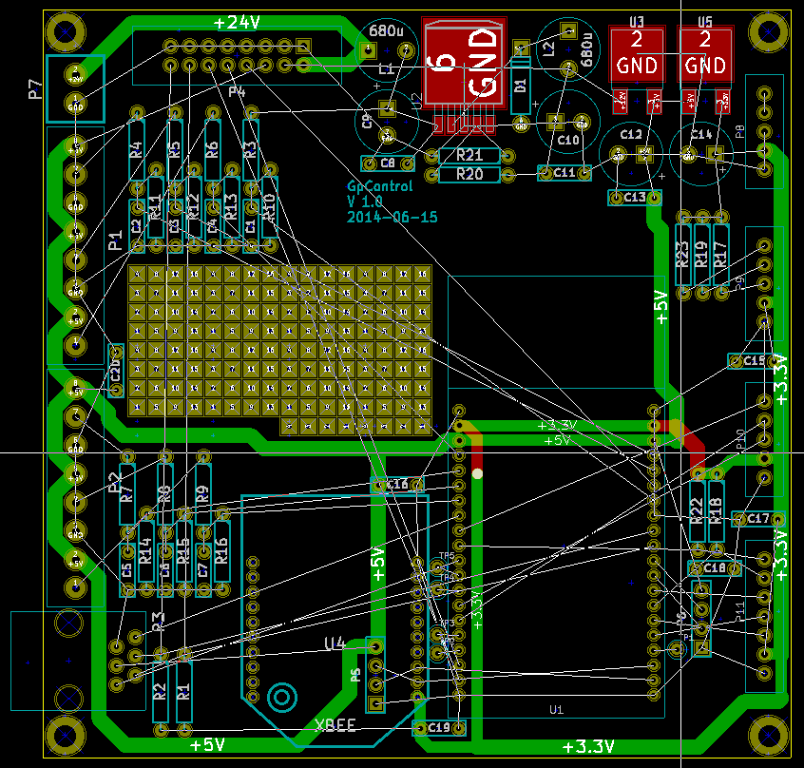
Simple control board using a 32bit ARM Cortex-M4 processor that can perform data logging and control. The unit is based on a pre-assembled ARM processing module ArmModMid which is plugged into a small motherboard containing the power supply, input/output circuits and other modules such as telemetry transceivers and GPS. The motherboard uses parts easily assembled by pupils and modifieable as required.
The 32bit ARM Cortex-M4 is a very capable processing unit much superior to PIC/Ardino systems. It has a 160MHz capacble processor with full 32bit support and floating point/DSP processing. It has 1MByte of flash memory for program storage and 192kbytes of RAM. This make it easy to program quite complex system relatively easily. As well as this it has a very good complement of hardware peripherals for things like USB,PWM,I2C,SPI,UARTS,TIMERS etc etc.
This is a project being done in my spare time in conjunction with the pupils at Chipping Sodbury School to produce a unit suitable for data logging and control for the Greenpower electric car challenge.
Capabilities
| Power supply | A filtered, switched mode power supply module that will take between 6 and 30V input for powering the system. |
| Analogue/Digital Inputs/outputs |
8 x 12bit inputs, 0-5V, with basic signal conditioning (level, filters). 6 of these are through screw terminals and two are designed to measure the voltage and current usage. There are additional channels available on the PCB that could be used with additional wiring. |
| Data storage | On-board micros SDcard for up to 64 GBytes of data logging storage |
| RTC | Battery backed up real time clock for date/time information |
| USB port | A USB mini-B connector for connecting to a PC/Laptop/Smartphone |
| XBee module holder | XBee radio transceivers module holder for Zigbee or 800/900 MHz radio telemetry modules. Connected using serial UART. If Xbee module is not used a serial port is available for connecting external devices. |
| Serial port | Serial port with 5V power for GPS module or other uses. |
| Display interface | A display interface port with an I2C bus and two user definable wires (switches/LED's ?) |
| Motor control interface | A GpSpeed motor controller interface port. This has 24V/12V and 5V power inputs, an I2C bus, two PWM output channels and a voltage and current input channel. |
| I2C modules | 3 x i2c bus module headers for items such as accelerometers, giro, compass and other such sensors or servo drive systems |
| SPI module | 1 x SPI module header for items such as accelerometers, giro, compass and other such sensors or servo drive systems |
| Breadboard area | The board has a small 0.1inch pitch breadboard area for additional electronics such as OpAmp signal conditioning circuits. |
Some information on the ArmModMid processor module:
| Processor | ST STM32F4 32bit Cortex M4 |
| Program memory | 1 MByte |
| Program RAM | 192 kbyte |
| Storage | Up to 64 GByte microSD card |
| RTC | Battery backed up realtime clock |
| Peripherals | 3 x 12bit ADC's (24 channels). 2 x 12 DAC, 17 timers, 4 x PWM, 2 x I2C, 2 x SPI, 4 UARTS, USB, CAN, digital I/O etc |
There are various software development environments for the ARM Cortex-M4 and especailly the STM32F4 processor that can be used.
However, we have developed a simple to use C++/C development environment based on the GNU standard C++/C compilers we have named ArmSys. This has: