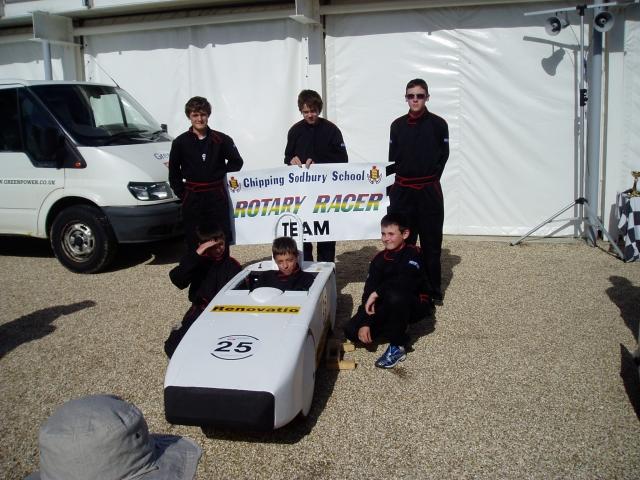
The Rotary Racer 8 is the new car being developed by Chipping Sodbury School's Rotary Racer Greenpower team. The team has been entering Greenpower races form many years, although the team members have changed as older pupils leave the school and new pupils and parents join the team.
The Rotary Racer 8 car's design was started in October 2008. We had a very successful year in 2008 including a couple of first places and coming 2nd in the national Greenpower championships. However, the lads were growing fast. We had to make modifications to RR7 for nearly every race to accomondate the growth spurts. RR7's design had reached its limit and we had to build a new chassis. We had also been learning more about aerodynamics with the use of VWT (Virtual Window Tunel) software and going to the wind tunnel at UWE. We had a number of design meetings, quite boring for the pupils !, to try and get our ideas in order for our new car. Some of our original requirements were:
A number of designs were proposed, the first being similar to RR7's vertical wing shape but wider to accomondate the wheels. A number of designs were tried in the VWT. 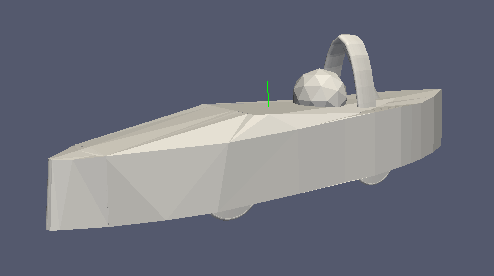 This design was eventually dropped as once it was widened to give, what we believe, a stable wheel track spacing its frontal area was much larger and its overal aerodynamic performance was no better than our existing car. It was also difficult to get the space for a larger driver with the batteries in rear and keep a tapered tail. Also the new Greenpower rules precluded the bodywork going over the eyeline of the driver so making full use of the predominantly vertical shape was difficult. So we tried turning the chassis design through 90 degrees to get the taper on the top and bottom rather than the sides. This allowed the wheels to be more easily enclosed and allowed the batteries to be positioned quite close to the rear of the car leaving a large space for the driver. We based the shape on a wing shape like
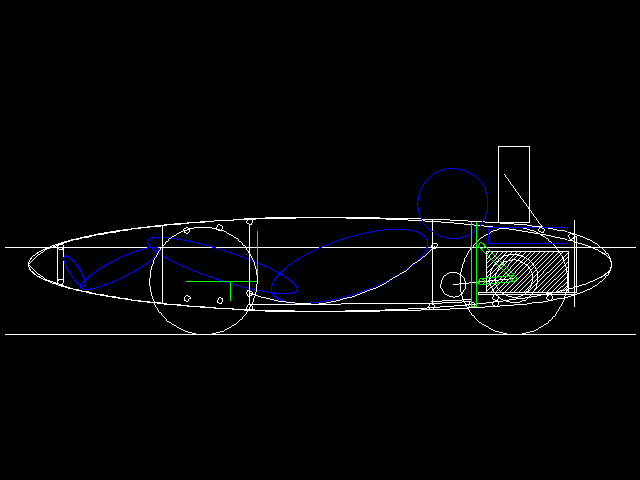
 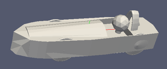 Solar powered cars and started with a simple elipse shape as this was easy to produce with a single bend in the aluminium tubes. We decided to go for semi enclosed wheels. This method was being used by a few Greenpower cars and allowed us to keep the overal width down while keeping a widish wheel track for stability. The overal frontal area, with a 600mm wheel track, was about the same as the existing car (RR7e). A bit of time was spent using the VWT to improve the core aerodynamics of the shape. CAD drawings were used to work out how and where to fit the necessary components such as batteries, wheels, motor and driver !
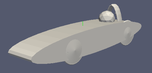
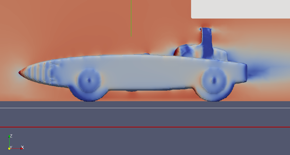
Eventually we had a basic design that had about the same frontal area as RR7e, but a much better body shape and semi-enclosed wheels. The VWT was telling us that it gave about a 25% reduction in aerodynamic drag over RR7e. Although we were skeptical of the VWT's results, at least it sounded that we were moving in the right direction. Also as the basic shape was like RR7 (although turned through 90 degrees), it was deemed easy to make using the aluminium tube method we had used in RR7 and previous cars. We were thus relatively confident that we could build it in a reasonable time. The VWT was used by some of the lads and dads during this stage. We continued with fine tuning the shape a bit, rounding off areas, using the VWT to check results after each modification.
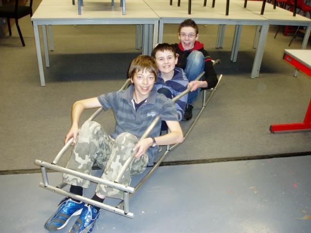
The cars chassis was built in a similar manner to the previous cars. It was made using a space frame made from 25.4mm x 1.6mm aluminum tube connected using plastic bungs with aluminum triangular plates used to strengthen some corners. This is the same basic method as used in the standard Goblin Greenpower cars. It is relatively easy for the pupils and parents to do. The tube was bent to an aerofoil type shape and fixed together.
Money was quite tight this year due to the economic climate, but thanks to some work getting sponsership from the local Rotary Club and Towns Land's Charity together with a days bag packing at Morisons we had a reasonable about of money to build and race the car, about £900. Though funds were still quite tight so we dismantled our old RR6 car for some tubing and other parts. The cars base and top was made using 4mm plywood with an additional layer of 4mm plywood at strategic points. The car's body to the sides was made using insulation foam so we could shape it easily. This is an experiment as we have not made a proper shaped body before. The side panels are removable so we can modify them later easily.
The cars weight is about 52 Kg, about the same as the RR7e car. With batteries and driver the all up weight is about: 148 Kg, depending on how many bacon baps the driver has had !
The nose cone and rear taper was made of layered impact foam as per RR7. This gave a degree of safety in the case of frontal or rear impacts.
The Joystick steering assembly was designed and built from scratch. We could not use the steering system from RR7 as we needed to get rid of the cross bar so that the lads legs could go past the steering. We also wanted to put the brakes on the front. Our existing wheels had disk brake mounting holes so we went for cycle disk brakes. We used relatively low cost Avid 5 Ball Bearing disk brake units and made a brake balencer to allow them to be operated by a single lever on the joystick steering system. The steering systems design was based on using 10mm rose joints as the bearings and 25.4mm steel tubing and machined steel parts.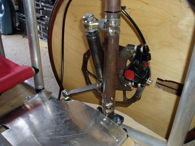 After much web trawling we decided on a 14 degree camber angle and 4 degree caster angle.
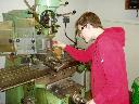 The kingpin camber angle was set so that their pivot lines hit the floor 10mm inside from the tyre center line. This gives some feel but was set to be fairly insensitve to bumps. The kingpin caster angle was set to 4 degrees backward to give a degree of caster. Note that the camber angle also gives a degree of self centering, but in a less stable fasion and also lifts one wheel slightly more than the other when turning. The steering arms, to the wheel mounts, are inclined inwards for Acherman steering. This angle was calculated the Ackermann steering calculator at: http://www.eland.org.uk/steer_download.html. The design called for a degree of Lathe, Milling and MIG welding work. Most of the components were made by the lads together with some welding.
The wheels were taken from the old car. They are 20inch cycle wheels made up for us at the local cycle shop, Terrys Cycles. The wheels are filled in with thin ply and use good quality Hope hubs. We use thin, high pressure tyres installed to give low aerodynamic drag and low rolling resistance.
The rear axle assembly was made using a welded steel subframe as per RR7. This 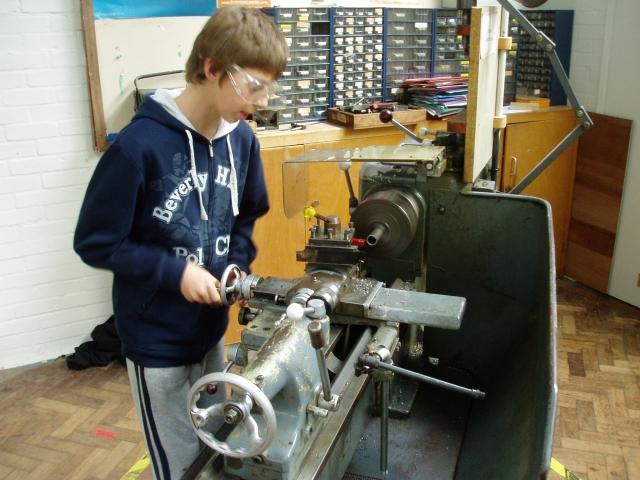 allowed the axles to be effectievly within the battery compartment area. The position of the axle was set in order to get an aproximately 40/60 ratio in weight balence to the wheels.
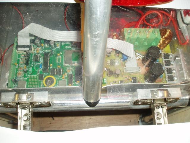
The battery installation system is basically the same as for RR7 as this worked very well. It is a bit like a roll-on roll-off ferry. The back of the car hinges downwards and allows the set of two batteries to be easily slid out and in. A single plug and socket is used to connect the batteries for safety, ease and speed. The battery packs were made of two batteries connected using a piece of ply and packing tape (the thickish, 10mm wide plastic tape that is tensioned and crimped together with a machine). The size and position of the battery compartment door was choosen so that it would hinge and rest on the ground to provide a loading platform for the batteries.
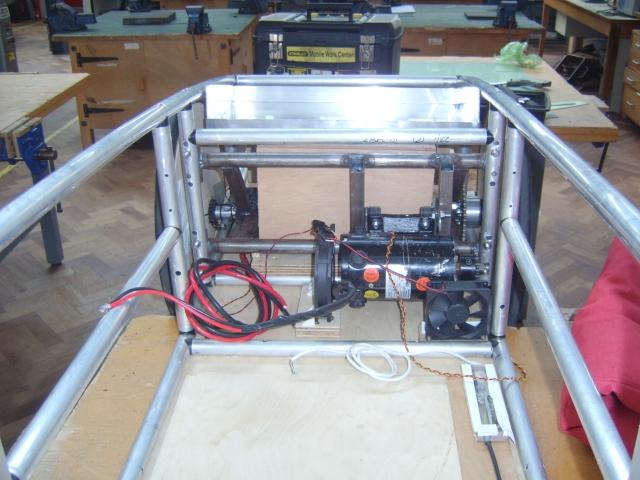 The motor mount is improved for RR8 from that used in RR7. It is mounted, car alternator style, to the rear subframe using two strips of angle steel bolted to the motors mounting plate. It pivots on two bolts at the bottom and is fixed in position with a single bolt running in a slotted arm at the top for adjustment. This allows for much easier and quicker chain tension adjustment when changing the fixed gears. It employs a simple fixed gear chain drive to a single wheel using 3/8 inch chain and chain wheels.
The seat is also the same hamock style used in RR7.This is made of a canvas material with web strengthening. In general, apart from the steering and external shape, the design was an evolution of previous Rotary Racer cars. There are more pictures on the building of RR8 here and here.
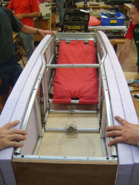
The aluminium and steel tubing forms a space frame cage around the driver and also forms the top and bottom shapes of the car. 4mm plywood is attached to the tubes using CS self tapping screws. For the sides of the car we needed a more rounded shape (from wind tunnel testing). We had used Jackador foam insulation for producing test models for the window tunnel at UWE. This was relatively easy to shape although a bit soft. We decided to have a go using this and perhaps change to another material in later years. The foam was attached to the sides using screws which screw into 6mm plywood plates glued to the foam within small routed areas. The foam was split into three sections per side. This allowed the sections to be individually removed for easy access to the cars internals when required.
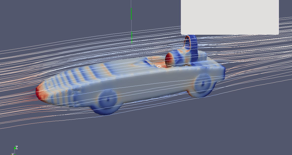
We spent a fair amount of time using our Virtual Wind Tunnel both during the initial design phase and after to optimise and develop the car. We had tried out software with the RR7 car in conjunction with testing on Kemble airfield and the simulated results matched the real results quite well. The VWT is web based and has a simple interface that allows the pupils to use it relatively easily. We used both the Blender and Pro/Desktop 3D CAD tools to enter design models. It helped with improving our understanding of aerodynamics and improving the cars performance. Unfortunately we have not had the time to do real trials with the car to validate the VWT as yet.
The car employs the Car Computer, Motor Speed controller, data logger and telemetry system from RR7.
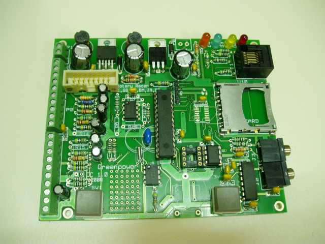
The software and electronics are being continually updated but the current system performs the following functions on the car:
We are using the CarComputer/MotorSpeed controller combination instead of having a gear change mechanism to keep the car running at optimum speed for a race. We over gear the car a bit, by choosing a suitable fixed gear ratio and then let the Car Computer manage the motor speed to keep the current averaging at the 25 Amp level. The idea is to gear the car so that the motor speed controller runs the motor at about 90% of full voltage normally. This provides a +-10% power range. In effect this provides a similar ability to having a continuously variable gearbox over a 20% gearing range. This is quite suitable for the nature of a Greenpower car.
The electronics have been designed for efficiency. The total power consumption of the Car Computer, Display and Motor Speed Controller is: 0.48 Watts which is about 0.08% of the total Greenpower Car's power consumption. As a comparison the power consumption of the solenoid we used to use to switch the motor on with RR6 was: 9.6 Watts, about 1.6% of total power !
The electronic speed control when switched fully on is about: 98.88% efficient. When operating at 90% voltage level its efficiency drops to about: 97.5% (Needs accurate testing ...). When geared and controlled like this the motors efficiency also drops a little, by about 1%. This compares very favourably with chain drives (about 97%) and gearboxes (could be as low as 90% depending on design, a good one is about 94% efficient).
So far the car electronics is working well. We haven't had the motor speed controller blow up yet, apart from a prototype unit which did go up in flames ! We do have a backup solenoid, just in case.
The data logging has proved to be invaluable for us to know how well the car is doing. It, with the telemetry system, allowed us to gear the car nearly spot on for the first race with no previous testing apart from the parctice lap data. We have used this as a tool to measure incremental performance gains as we try and improve the cars performance. Some info on the data logs is: here
The lads also got involved in designing, building and programming a computer (Picaxe) based car horn. Amoungst other tunes this could play Barbie Girl and other such dities :)
The car was completed just in time for the Goodwood Southern Counties race on the 12th July 2009. It took quite a lot of extra work in the last couple of weeks to complete it with the Lads and Dads doing work in various garages as well as at school. It arrived at Goodwood untested, apart from 100 years up and down a track, and with no logos or stickers as the paint had yet to dry ! We had intended this race as a testing day. However, the car was going so well and running in second place that it quickly turned into a real race. Apart from a jamed motor cooling fan and some other minor issues all worked very well. We came in second place by about 40 seconds, an excellent result for its first outing.
Speeds
Equivalent Petrol consumption:
Costs
Time for building
Electronics
Virtual Wind Tunnel
The cars design and development was solely funded by our sponsors either financially or by giving us materials to use. The cost of building and racing this car was about £740.00 using the drive batteries, motor, electronics, and wheels from our old car. Our main sponsors are:
We will continue to develop the car during the season, improving aerodynamics and other bits.