
Account
Pictures

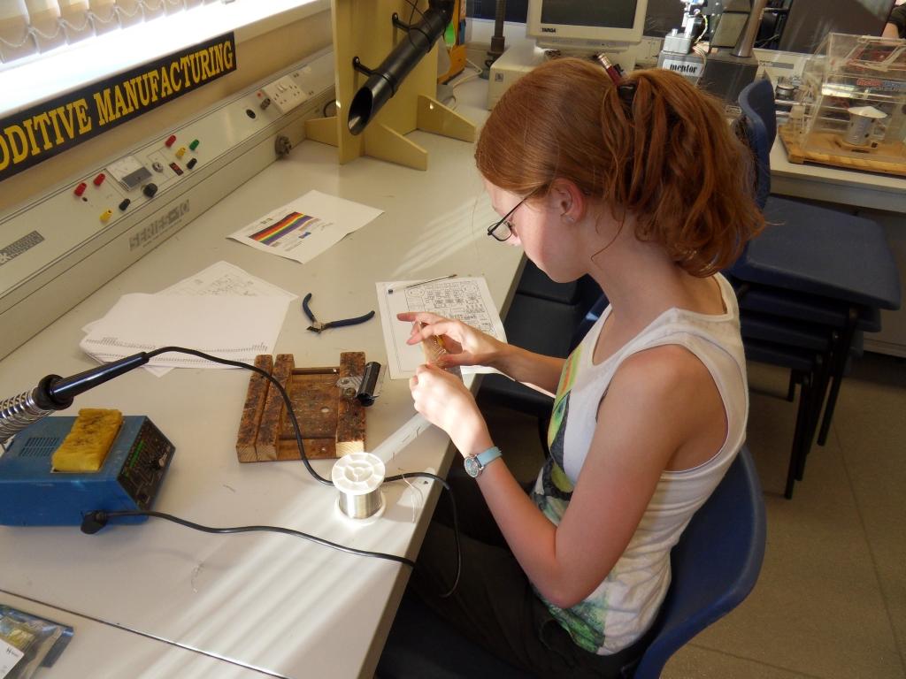
Pulling away from the starting grid
Greenpower Buck Boost Controller
Purpose
It was the winter of 2011. the older RR pupils had reached 17 and wanted to continue doing GP in the F24+ challenge. We were about to build a new car for F24 and building two cars at the same time and managing them during the year was not a possibility due to finance and time. So a deal was struck between the older three lads and the newer and younger F24 team members. The older lads would design the new RR9 car while the F24 people would do the work needed to get RR8 suitable for competing in F24+ alongside F24 as well as modify it for the 2012 rules.
One of the challenges was how to use the additional power that F24+ provided due to the shorter race times per set of batteries. The typical way would be to change the cars gearing so that it would go faster with the higher average current available. With our fixed gear drive in RR8 we had to change the motor cog. Unfortunately the amount of travel on the chain adjustment was not enough to handle the big change in gear needed but it was modified to cope. However gear changes did take quite a time and would have to be done under quite tight time constraints. We would have to change the gear after the practice session (practice by F24 members was a high priority) and then after the F24+ race ready for the F24 race. This would lead to less practice time and the F24 members disadvantaged due ending up further down the starting grid and possibly starting after the race start if things didn't go well.
With this issue and the fact that we hadn't done any electronics with the pupils in the last year, it was decided to have a go at an electronics based solution. We generally over gear RR for a race and back off the voltage to the motor using a buck mode speed controller. Quite a few teams use this PWM type of controller. On average this runs at about 93% of voltage allowing us to slow down as well as speed up a little. So we could gear the car for F24+ and set the speed controller to reduce the voltage to say 18V or whatever for the F24 race. This has two disadvantages:
- The motors efficiency is reduced as the current through it increases due to heat losses in the armatures copper winding. This loss is I^2 x R (Current squared times resistance of copper winding). For us to use the same average power from the batteries at this reduced voltage the motor current would be proportionally higher and hence the motors losses would be higher and the car would not go as well.
- With the higher gear there would have been the possibility of the car going very fast in F24 during downwind/downhill sections. We considered this unsafe for all.
One way to over come this was to use a Buck Boost speed controller. What this effectively is is a conventional buck converter that can reduce the voltage followed by a boost converter that can increase the voltage. As mentioned earlier the copper winding losses in an electric motor are proportional to the square of the current flowing through it. Also the motors peak RPM is proportional to the voltage applied (There are other factors that affect this). So if we can increase the voltage we could run the car at F24+ speeds while keeping the gear ratio the same as for F24. There was also a benefit that because we would be using a higher voltage the current through the motor would be less than if we had geared the car for F24+ (power levels would be the same). Due to the increased efficiency we could end up with slightly more power at the wheel. However, boosting the voltage would take some energy and the increased RPM of the motor would lead to commutator losses as well as bearing losses. We thought that overall this should balance out and may be we could get a touch higher overall efficiency if we engineered it all right but it also might go the other way.
How it works
Buck mode circuits and to a more limited extent boost mode circuits are in use in most electronic devices today. They offer a high efficiency way of lowering or raising voltage. A typical device, such as a mobile phone, will require many different voltage rails. Maybe the battery is 3.7V. This will need to be reduced to 3.3V for some of the components, perhaps 1.0V for the CPU and 1.5V for the memory. It will probably need to be boosted to 5V for the USB and higher for the display lighting and flash. They are prevalent in computers, touch pads, TV's in fact most items as well as being used for higher power uses such as motor drives.
The basic operation is quite simple once you understand the basics of electronics. This is a very basic and rough description, please read up on electronics :). The core things to understand are listed below in basic terms with a rough analogy to a liquid in pipe system:
- Voltage: This is the electric potential between two points and what moves electrons around a circuit. It is like the "pressure" of a liquid.
- Current: The amount of electrons flowing around a circuit. It is like the amount of liquid flowing through a pipe.
- Resistance: Something that resists the flow of electrons. Can be thought of a narrow pipe that restricts the flow.
- Capacitance: Two metal plates close together. Stores electrons to provide an electric potential. Like a small battery. Can be thought of as a high up liquid tank.
- Inductance: A coil of wire. Current flow induces a magnetic field and visa versa. Can provide something like "inertia" to the flow of electrons as energy passes from current to the magnetic field and back again. Can be thought of as inertia of a liquid when moving.
Here is a basic block diagram of a boost convertor.
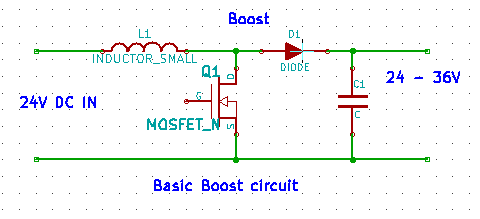
L1 is a simple coil of wire. Q1 is a MOSFET switch. Basically it switches on between the drain (D) and source (S) terminals when the gates (G) voltage wrt to its source is greater than about 4 volts. The Diode D1 only allows electrons to flow one way. C1 is a capacitor that stores this electron charge which is then passed out and through the motor.
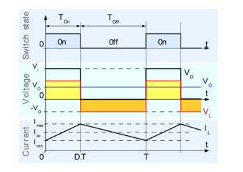
Initially Q1, a MOSFET switch, is off. When the 24V input voltage is attached a current will flow through the inductor L1 and the Diode D1 to charge up the capacitor C1. This voltage will be available at the output. Now Q1 is switched on and off continuously at a relatively high rate say 40kHz. When Q1 switches on the current through L1 starts to rise in a ramp like fashion. The inductance slows the rate of rise of the current so it is a ramp. At some point Q1 is switched off. However there is still a current flowing through L1 (the magnetic field collapses keeping the current flowing). This leads to the voltage (based on the number of electrons) to rise. This higher voltage creases a current that flows through D1 and changes the capacitor up to a higher voltage. The duty cycle (the ratio of how long Q1 is on to how long it is off) determines the overall amount of voltage rise.
See Wikipedia and Internet in general for both an overview and more detail on buck and boost convertors as well as electronics.
For those oldies who know about old fashioned car ignition systems that generate the spark for the spark plug. The L1 is the coil and Q1 is the contact breaker. There is no D1 (as DC (direct, one way, current) is not needed) and C1 is the spark plug. The only difference is that the coil has additional windings past where the contact breaker is connected so that the boost voltage generated is a lot greater. Nothing much is new :)
Some info on how buck and boost convertors work:
- http://www.ecircuitcenter.com/Circuits/smps_buck/smps_buck.htm
- http://www.youtube.com/watch?v=FT_sLF5Etm4
- http://mike-thomson.com/blog/?p=246
Buck Boost Block Diagram
.png)
This shows a basic block diagram of a buck boost speed controller. In our design the diodes are actually MOSFET's the same as the two main switching MOSFET's, but the basic idea is the same. We use a single inductor which is shared between the buck and boost sections to save needing two. In Buck mode Q2 is off and Q1 is switched on/off at about 40kHz. In Boost mode Q1 is switched on solid and Q2 is switched on/off at about 40 kHz. In buck mode the inductor L1 and C2 smooths the switching waveform to provide a filtered DC output from 0 to 24V. In Boost mode the inductor is "charged" up when Q2 is on and then releases its energy into C2 when Q2 is off to provide a voltage from 24V to perhaps 36V. The duty cycle of the Q1 and/or Q2 switching defines the level of voltages produced.

See Wikipedia and internet for overview of Buck and Boost convertors:
In our speed controller the MOSFET gates are driven by a small PIC microprocessor's PWM outputs via MOSFET gate driver IC's.
In terms of complexity it is only slightly more than a conventional buck speed controller having two additional MOSFET's. In a basic buck convertor, driving a motor, the inductor can be eliminated as the motors self inductance (it has a coil of wire on the armature) will suffice although this is not ideal.
Circuit Diagram

Circuit Description
Our circuit was designed so that the pupils would have maximum involvement in the production of the unit. Most of the components used are big and mainly through hole ones, however there are some larger sized surface mount components included. There is a small PIC CPU of the type used in the school DT labs to act as a simple controller to generate the PWM signals. The input to the board is a PWM signal from the cars computer control board which defines the voltage/power level. It can also take a voltage from a simple potentiometer. There is also an I2C interface (simple digital communications) that accepts commands to set the boost level from 100 to 150%. When set for 100% the controller will only act as a buck convertor. The level of boost level sets the maximum voltage boost that can be applied.
The core buck/boost circuitry is to the middle right. Most of the rest of the circuit is then the gate drive IC's driven by a set of delays to make sure the MOSETS don't switch on together and the additional control circuits. As well as the Buck/Boost circuit there is a transient safe 12V power supply, PWM drive for the motors fans and the main current measurement Hall Effect device for the data logging and current control. So there is quite a bit more on here than is needed for just a buck/boost controller.
The gate drive IC's perform a few functions. One they strongly drive a voltage onto the MOSFET's gate for quick switching. Two they generate a 10V "boost" voltage that enables them to drive the MOSFET's gate 10V above its source connection. Three they roughly monitor the current through the MOSFET and switches it off if it exceeds a set value for MOSFET protection.
All of the components are relatively cheap and readily available.
We did add a small circuit to allow the "high side" MOSFETS to be switched solidly on for better efficiency. This is not shown here (it as a small PCB made in the DT etch tank and glued to the back of the main PCB).
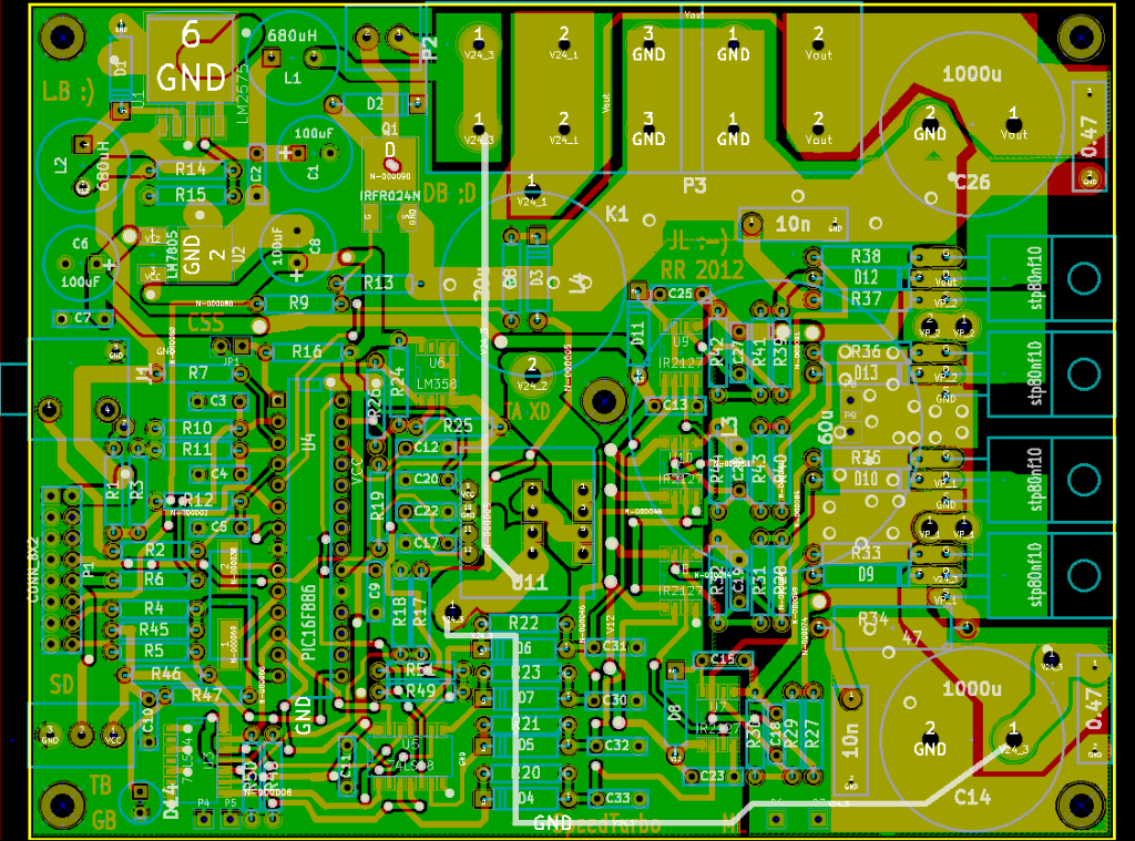
PCB Layout
Components
Most of the components were relatively standard and low cost. The whole controller cost about £70 to build including PCB. The only special item was the Inductor. This was made using a length of 3mm (?) diameter enameled copper wire wound around a piece of 1.35" household drainage plastic pipe. There were about 3 layers of windings held together with epoxy glue. It was an air-cored inductor to simplify construction. MOSFETS actually used were: IRFB4110PBF.
Building
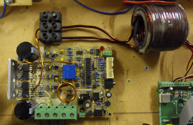
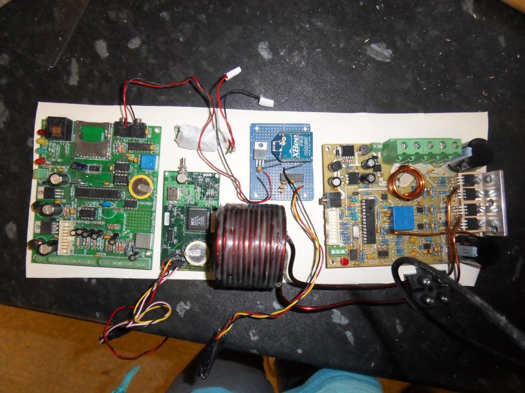
The placement of the main components and the high current power tracking around the MOSFETS and power connector was done by an adult engineer, but otherwise the PCB was predominantly tracked out by the pupils in 15 minute stints. All of the younger team members did some of this work guided by the older students who had tracked out PCB's before. You can see the initials of the students involved on the PCB. There are some pictures at:
http://www.greenpower.beamweb.co.uk/showcase?cmd=view&id=73


Once the PCB was tracked the design was sent to Newbury electronics for a two layer PCB to be made. This cost about £35 in one off. In the past we have made the PCB in house using the etch tank available, but time was short. Once the PCB arrived back the components were soldered in place by the pupils.
Testing
The basic board was tested using the schools battery/motor test rig and then really tested during the 2012 season with RR8.
The contrroller was also used in RR9.
Difficulty Level
Designing and building a basic buck or buck/boost speed controller is fairly easy. Certainly year 7 and upwards can help track out the PCB's and build them and some older pupils can do schematic design work etc. There is no detailed knowledge or exotic mathematics or components needed. There are few design considerations around the MOSFET's due to the current levels involved though as with any MOSFET controller. These are:
- Make sure the PCB tracks carrying the motor current are: short and thick. We used about 1cm tracks but soldered lengths of the copper core of 30Amp ring main cable onto them to make sure.
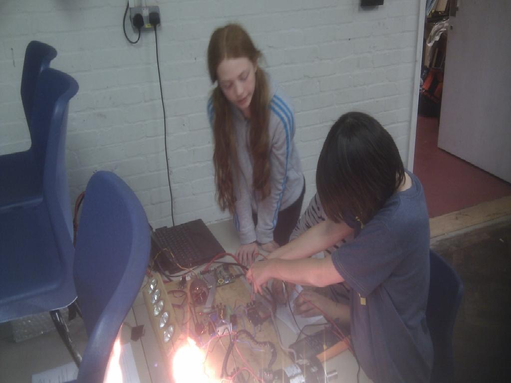
- You have to make sure that no "ringing" voltages can occur in the MOSFET source/gate drive circuit. If the gate/source voltage exceeds about 20V even for less than 1us you will likely get the random "Fire Emitting Transistor" failure. This is the main problem that newcomers get. You have to be careful with you PCB tracking to make sure this does not happen.
.png)
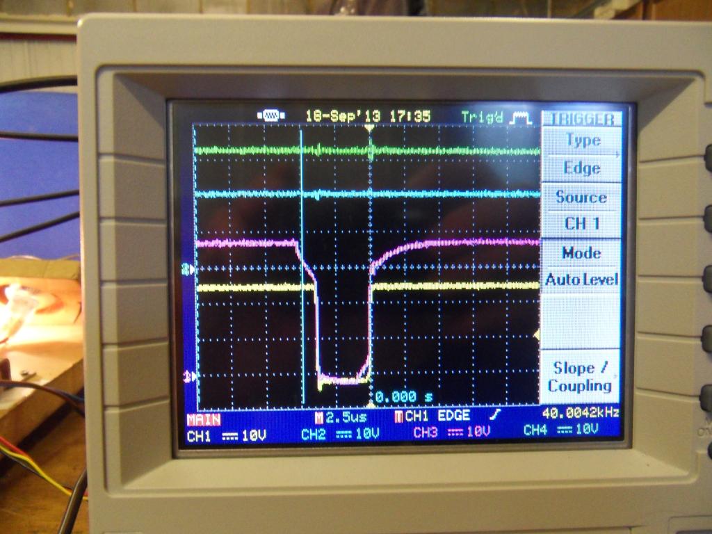
The inductance in the power supply to the MOSFET legs can create large voltage spikes:
![]()
The circuit design took a few hours, the PCB tracking and building took about 3 Greenpower two hour sessions with two pupils involved at a time.
You do need a design to work from or an electronic engineer to help you with the design. Of course, as with all engineering things, the basics are quite simple. It is when you get into the detail when you design things for the real world that things get tougher. For example improving the efficiency, making it smaller, proving its reliability, reducing electromagnetic emissions, making it cheaper etc. Lots of science and mathematics and testing. Also real world voltage convertors/motor controllers can be challenging. They are becoming more prevalent. Just look at the modern cars electrical/electronic systems with window motors, central locking ECU's, heated screens etc etc. Look at the bigger uses, imagine designing a motor speed controller for an electric train, now that is hard! Also in the real engineering front land, how about extremely high power, high voltage, ones which allow the power from the wind turbines off the coast of Scotland to be sent to southern England over high efficiency DC power lines. That one is still being worked on. One of the major industries needing electrical and electronic engineers is the power industry ...
Efficiency
The efficiency of the controller is down to a few basic things:
- The on resistance of the MOSFET's. The current flowing through a MOSFET's on resistance causes heat to be generated and thus power lost. We have used very low on resistance MOSFETS in the order of 0.004 ohm. The loss per MOSFET is about 2%.
- When a MOSFET switches its resistance goes from high to low. During the changeover, which can be 100's of ns, there is quite a high resistance with a reasonable current flow. This causes heating and thus power loss. To reduce this you need to drive the gate hard and fast, against the capacitance of the MOSFET's gate and other stray capacitance hence a gate driver IC. One issue with switch fast is that it cause large transients in the main current path which can cause the MOSFET to blow due to the above. So there is a trade off between efficiency and reliability.
- A higher frequency of operation allows smaller inductance's and capacitance's to be used, but increases efficiency losses due to switching as there are more of them.
- The Inductor has a degree of resistance and thus heats up with a power loss.
- Power loss due to controllers electronics.
Overall the original buck only mode controller was about 98% efficient and the buck boost about 94% (in buck mode) due to the extra MOSFET and Inductor in the path. The efficiency in boost mode was probably around 92%.
Actual Performance
We used this buck/boost controller during the 2012 season on RR8 and in the 2013 season in RR9. Unfortunately we did not get to do much real performance/efficiency testing due to the work involved in designing/building RR9. We did find a bit of time later in the 2013 season though to do some quite efficiency tests with our battery/motor test rig and also there is the race performance from looking at our data logs.
Efficiency Tests
| Batteries | RR1,RR2 (practice set) |
| Motor1 | RR1: Old RR8 motor with holes |
| Motor2 | RR2: Old RR8 motor with fixed magnet |
| Bulbs for tests | 2 x (4 x 50W) |
| Measurement Resistors | Farnell: 120-0373 0.005 Ohm, Voltage to Current factor: 200x |
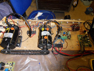
We used our basic battery and motor test rig to carry out these tests. With this we have two GP motors connected with a drive chain. The second motor acts as a generator and drives sets of 12V 50W halogen bulbs. For the tests we used two sets of 4 bulbs. We used some low resistance precision resistors in series with the current from the batteries and through the bulbs at the output in order to measure the current accurately. A single digital DVM was used to measure the voltage across these resistors (in mV) and the input and output voltages. The current could be calculated and hence the input power and output power. The overall efficiency is the ratio of output power to input power.
The motors are about 74% efficient at the speed/current we use them. As there are two in series we would expect to see an overall efficiency of 0.74 * 0.74 = 0.54 (ie 54%). This was close to what we saw. However we only consider the differences in efficiency between tests rather than the absolute efficiency as really the motors actual efficiency is not known accurately and these are old motors one that has been fixed (reglued magnet). Also our test rig is a bit basic :)
Test 1
The “old” speed controller as used in RR8.
| Power | InVolts | InAmps | InPower | OutVolts | OutAmps | OutPower | Efficiency |
|---|---|---|---|---|---|---|---|
| 100 | 23.5 | 17.8 | 419.71 | 15 | 15.92 | 238.8 | 56.8% |
| 95 | 23.5 | 16.7 | 392.45 | 14.4 | 15.52 | 223.4 | 56.9% |
| 90 | 23.6 | 15.2 | 358.72 | 13.6 | 15.0 | 204 | 56.8% |
Test 2
The “new” boost speed controller as used in RR8/RR9. Boost level 100.
| Power | InVolts | InAmps | InPower | OutVolts | OutAmps | OutPower | Efficiency |
|---|---|---|---|---|---|---|---|
| 100 | 23.7 | 18.6 | 440.8 | 14.7 | 15.08 | 221.6 | 50.2% |
| 95 | 23.8 | 16.9 | 403.6 | 13.8 | 14.52 | 200.3 | 49.6% |
| 90 | 23.8 | 15.1 | 360.8 | 13.0 | 14.22 | 184.8 | 51.2% |
Test 3
The “new” boost speed controller as used in RR8/RR9. Boost level 128 giving about 28.5 Volts to the motor.
| Power | InVolts | InAmps | InPower | OutVolts | OutAmps | OutPower | Efficiency |
|---|---|---|---|---|---|---|---|
| 100 | 23.7 | 27.68 | 656.0 | 18.7 | 17.96 | 335.8 | 51.2 |
The newer speed controller was quite a bit lower in efficiency due to the extra MOSFET and Inductor in the main current path. Mind you there was a dodgy solder joint on the board that led to the final MOSFET being left switched off and acting as just a diode reducing the efficiency in F24 further. This was fixed later and the efficiency drop was about 4% rather than 6%.
Anyway the overal input to output effciciency difference between buck and boost mode overal was negligable on the new speed controler and is 5% down on using our older buck controller. What we haven't done is compare this with gears, we need to do that next. However we can look at the motor graphs. At 30 Amps the motor is about 70% efficient while at 18 amps it is about 74% efficient. So roughly it looks like we gain 4% and lose 5%.
Race Performance
We used the buck/boost controller for some races in 2012 and used gear changes in others.
We used the older buck mode controller in the following races with manual gear change:
- http://www.greenpower.beamweb.co.uk/files/RotaryRacer/performance/2012-06-10_Goodwood/
- http://www.greenpower.beamweb.co.uk/files/RotaryRacer/performance/2012-09-30_CastleCombe/
- http://www.greenpower.beamweb.co.uk/files/RotaryRacer/performance/2012-10-14_Goodwood/
We used the buck boost mode in the following races so no gear changes:
- http://www.greenpower.beamweb.co.uk/files/RotaryRacer/performance/2012-07-16_Rockingham/
- http://www.greenpower.beamweb.co.uk/files/RotaryRacer/performance/2012-09-15_Merryfield/
It is difficult from the F24+ figures these to see any real differences. At Rockingham we averaged 55kmph at about 29 amps, At Merryfield we averaged 52.7 kmph at about 28,7 amps both with boost. At Castle Combe we averaged about 49.6 kmph at about 28.3 amps, at the final we averaged 52.4 kmph at about 27.4 amps. Rockingham is a fast circuit and Castle Combe is a bit hilly. The races are on different circuits in different conditions and perhaps different drivers and pit-stop strategies. from what we can see there was no noticeable difference in that using the buck boost controller gave about the same overall efficiency as using a gear change.
I think that with very careful design, experimentation and increase the voltage further you may be able to get a few percent of increased overall performance, but I don't think it would really be significant when compared with, say, the aerodynamic design of a mirror on a Greenpower car.
For the 2012 final we decided to use gear changing as the efficiency of the buck/boost system was definitely less than our older buck mode controller in F24. As the drivers were well practiced by then and the fact that our grid place was guaranteed the benefits of gear changing outweighed the convenience of using the buck/boost controller.
We only used the buck/boost controller during the 2013 season in RR9. Although we did purchase and drill the grub screw holes for the gears for F24+, we didn't have enough time to fit the old controller back in. All of our time was spent improving the basic new car. So we knew efficiency would be impaired in F24 but expected F24+ efficiency to be only slightly less than if we had used a gear change. We had planned on trying to designing/making a more efficienct version in 2014.
Purposely we only used the controller only as a buck controller in F24 because as a leading car we thought that people would get the wrong idea with the word "boost", as it appears some have. Unfortunately buck/boost controllers are now banned in Greenpower due to the misunderstood idea that they will provide a high degree of overall efficiency increase and hence a significant increase in car speed. Anyway it was an excellent, fairly simple engineering project that enabled our pupils, to build one and see this technology in use.