
Account
Pictures
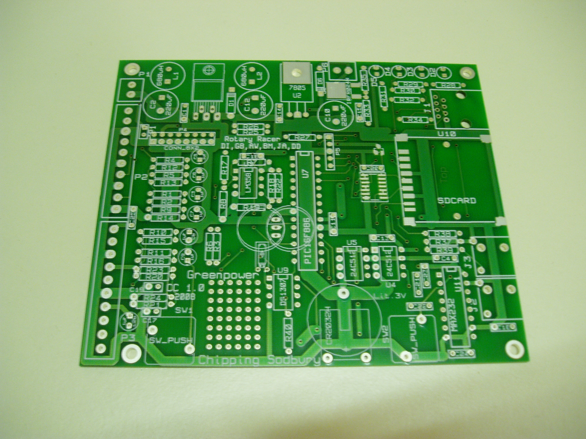
Greenpower Car Computer: Chipping Sodbury School
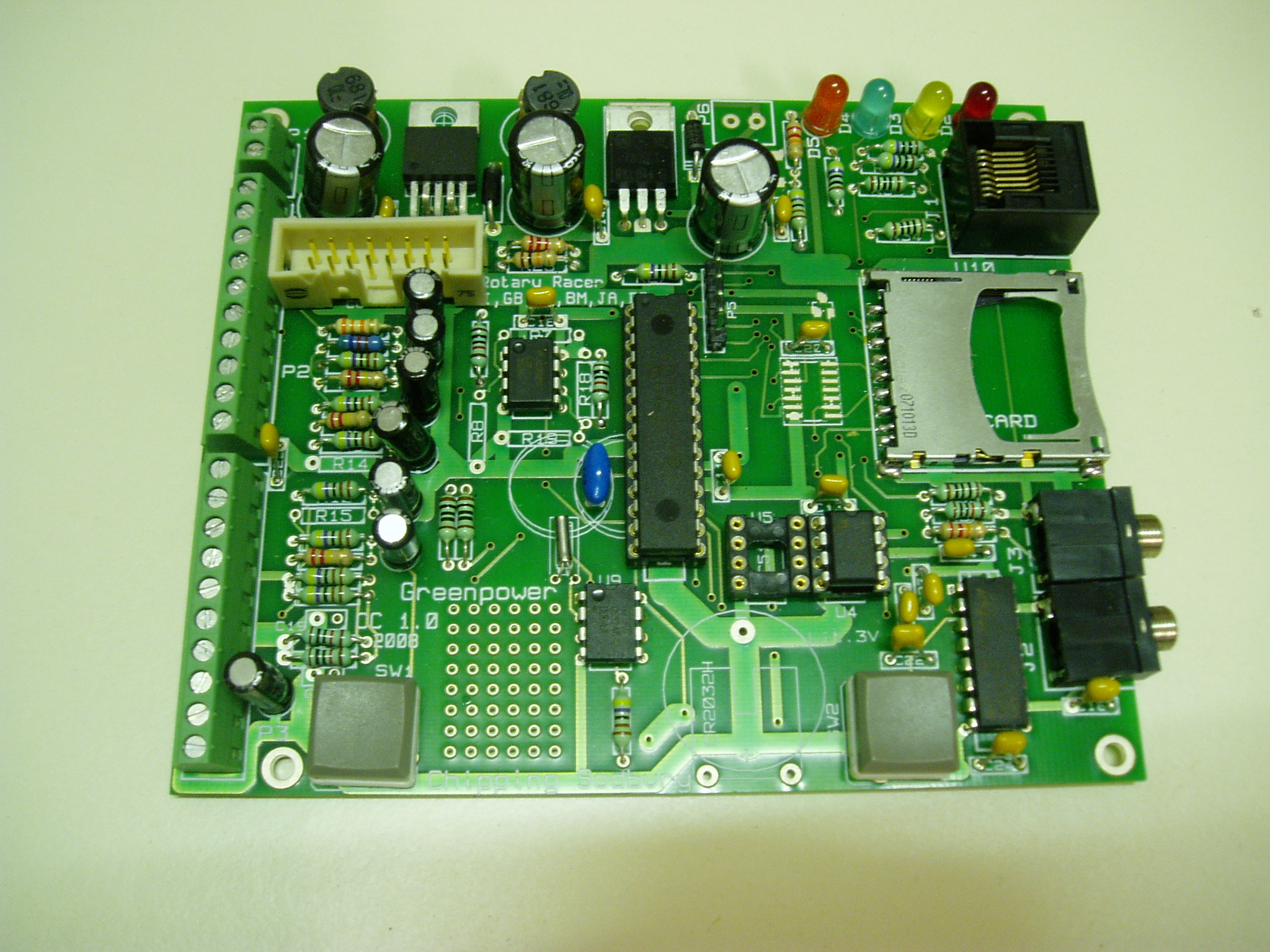
The main idea of this unit is to provide instrumentation, data logging and feedback for the driver and pit crew on the Greenpower electric cars performance. The board was specially designed for the purpose after experimenting with a small Picaxe development board. It's design was based on the Picaxe system that the pupils use at the school for microprocessor based electronic projects. It uses conventional through hole components with a few surface mount components added to demonstrate this packaging style and give the pupils a fine soldering challenge! The board is of sufficient size to allow it to be easily built by pupils.
Originally Rotary Racer cars, pre RR7, had no electronics, just a simple on/off switch. Rotary Racer 7 however, had the first incarnation of the Car Computer with Electronic Speed control module. The Car Computer was developed by a parent with the pupils helping. They helped with the research and produced presentations on the idea. A prototype design was built using the standard PicAxe computer modules that the school used for teaching purposes and played with in the RR6 car. The idea of this was to make the system so that the pupils could learn to program the modules in the future. After trialling the system, just data logging, in some races, it was decided to actually design a board with all of the components we needed to simplify the overall system and make it more reliable. A 2 layer PCB was designed, the lads did some of the PCB tracking, and the design was sent to a PCB company for manufacture. A number of boards were made for the teams at Chipping Sodbury School. The Lads and Lasses of the teams made up the boards and wrote simple Picaxe programs to test the boards functions. A separate Motor Speed controller was designed and built to be driven from the Car Computer. This employs high current MOSFET transistors as the PWM (Pulse Width Modulation) output. The design for this was challenging as the motor could draw up to 130 Amps. The PCB for this was made in the school, by the pupils, using the schools PCB fabrication facilities and the components installed.
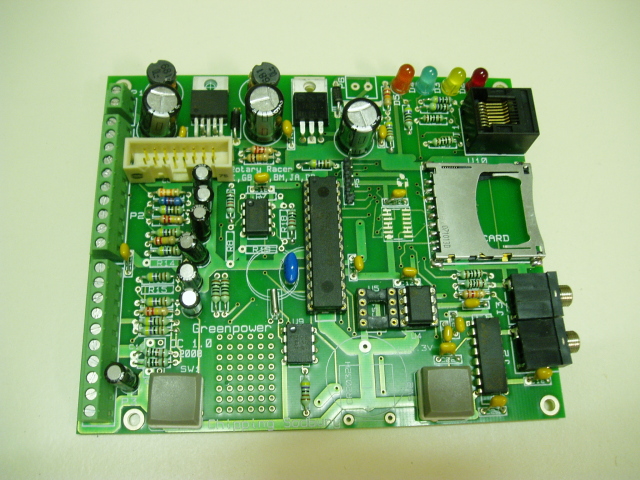
The core module is the Car Computer, this consists of the following:
- Simple, low power, PIC Microprocessor based computer board. Possibly mounted near to the battery and motor.
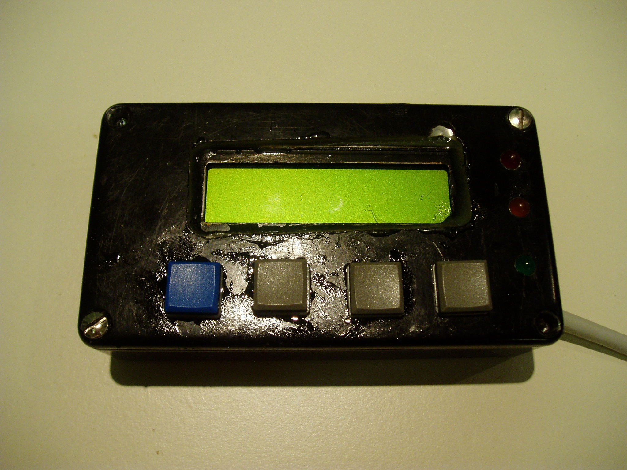
- LCD/LED driver display. This can be a 2 line by 20 character LCD display or some simple LED's.
- Some buttons near to the display.
- Sensors connected to various car components.
- Serial interface to Laptop computer to retrieve the data logged and to program the computer.
The design is flexible and with suitable programing can be used for various purposes. In typical use it can perform the following functions:
- Battery backed up real-time clock for date and time. This keeps the date and time for the datalogging so that all information has a date and time attached.
- Measure, calculate and display the cars current and average speed. A small magnetic or optical cycle computer wheel sensor can be used as a sensor for this.
- Calculate and display the distance traveled.
- Measure and display the battery voltage.
- Measure and display motor current.
- Measure and display the motors temperature.
- Log all of the data to non-volatile EEPROM memory for later recall.
- 3 LED's and/or LCD panel for driver information.
- Regulated power supply: Runs off car's 24Volt power supply (7 – 24 Volt operation). The board has a filter to reduce glitches on the power affecting its operation.
- Low power (Approx 15mA at 15Volts (0.22 Watts))
- Can be programmed in PicAxe Basic or 'C'. Both are free development tools.
- Serial RS232 communication to Laptop computer for data download.
- Operational Amplifier to scale and offset analogue signals.
It has options for implementing the following extra features
- Option for on-board high efficiency 24V switch-mode power supply regulator.
- Calculate and display the battery charge in % for each battery set.
- Control motor speed if motor speed controller is present. This can automatically set the maximum motor speed based on the charge present in the batteries and the race duration.
- Control the speed of a cooling fan for the motor to save power on this device.
- Store the data into a removable SDCARD that can store over a years worth of data sampled every second.
- Extra RS-232 port for live radio telemetry back to the pit crew and/or for GPS interface.
- Use a simple 2-line LCD panel for display with 4 user input switches.
- I2C serial bus for extensions.
- High current switch output to drive horn, relay, fan etc.
Some Features of the Car Computer:
- Easily built by pupils.
- Can be programmed using free Basic or 'C' software development tools under Linux or Microsoft Windows.
- Flexible, hardware can be modified for different purposes and there is a small patch area for extra components.
- High efficiency switched mode power supply built in with power line filters to reduce voltage spike interference.
- Low power requirements 0.21Watts.
- Real-time clock with battery backup.
- The processor has 25 pins available for digital I/O or analogue inputs. Up to 5 analogue input channels can be connected.
- Operational Amplifier and RC filtering for analogue signal conditioning.
- Simple screw terminals to connect power and inputs/output lines.
- Reset push button and user push button on board.
- Four LED's for development or other purposes.
- Daughter board connector for Motor Speed Controller or other purposes. This has power, I2C bus and PWM control signals.
- Display interface RJ45 connector. This has power, I2C bus and I/O lines available for LED and/or switch interfaces.
- Up to 64Kbytes of on board non-volatile FLASH memory.
- Interface to SD card for over 8GBytes of FLASH memory support.
- Two serial port jacks using PicAxe pin-out. One is a true RS232 interface, the other is a PicAxe bit bashed serial interface.
- Onboard MOSFET output for high current drive for replay, fan or other purposes.
Usage in Rotary Racer 8
The car electronics has been developed over the years from its first research and testing in Rotary Racer 6 and its real use in Rotary Racer 7 to its current incarnation in Rotary Racer 8. In RR8 we have the car computer, a motor speed controller, a display/control module, a Zigbee telemetry module and a GPS module. The GPS module was added when GP brought in the race speed limits. It allowed us to keep the cars average speed to within seconds of the speed limit for a race. The pupils used Google maps to get the grid corordinates for the start line on the various tracks. The GPS module then timed the car when crossing this point. It also had a secondary GPS location half way round the track for greater accuracy.
We are using the CarComputer/MotorSpeed controller combination instead of having a gear change mechanism to keep the car running at optimum speed for a race. We over gear the car a bit, by choosing a suitable fixed gear ratio and then let the Car Computer manage the motor speed to keep the current averaging near the 25 Amp level (depending on the batteries condition and temperature). The idea is to gear the car so that the motor speed controller runs the motor at about 90% of full voltage normally. This provides a +10% -100% power range. In effect this provides a similar ability to having a continuously variable gearbox over a 20% gearing range. This is quite suitable for the nature of a Greenpower car.
The electronics have been designed for efficiency. The total power consumption of the Car Computer, Display and Motor Speed Controller is: 0.48 Watts which is about 0.08% of the total Greenpower Car's power consumption. As a comparison the power consumption of the solenoid we used to use to switch the motor on with RR6 was: 9.6 Watts, about 1.6% of total power !
The electronic speed control when switched fully on is about: 98.88% efficient. When operating at 90% voltage level its efficiency drops to about: 97.5% (Needs accurate testing ...). When geared and controlled like this the motors efficiency also drops a little, by about 1%. This compares very favourably with chain drives (about 97%) and gearboxes (could be as low as 90% depending on design, a good one is about 94% efficient).
The electronics has worked exceptionaly well. We haven't had the motor speed controller blow up yet, apart from a prototype unit which did go up in flames ! We do have a backup solenoid, just in case.
The data logging has proved to be invaluable for us to know how well the car is doing. It, with the telemetry system, allowed us to gear the car nearly spot on for RR8's first race with no previous testing apart from the practice lap data. We have used this as a tool to measure incremental performance gains as we try and improve the cars performance. Some info on the data logs is: here
The telemetry added a new angle. Using an old Linux laptop from the trackside the rest of the team can monitor the cars performance, check battery levels and motor temperature as well has see race lap times and average speed. The telemetry is bi-directional and allows tweaks to the average current setting to be made.
The software was developed continually from race to race. This was now written in 'C' using the free SDCC compiler as more sophisticated use of the PIC was required (Interrupts). The 'C' language was now a bit beyond the pupils understanding levels and so was mainly done by the adults involved. However, the pupils were shown what the code does and in post race meetings we went through the data logs and issues with the electronics and possible improvements. Some of the lads came up with improvements to the system like the bright blue flashing LED to tell the driver to pit-stop after some drivers missed the pit board and implemented some of the bits necessary.
During the development of RR8, the lads also got involved in designing, building and programming a computer (Picaxe Basic) based car horn. Amoungst other tunes this could play Barbie Girl and other such dities :) They are now implementing an improved version and two of the lads are writing bits of 'C' code to do this.
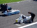
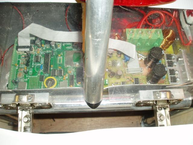
This picture shows the Car Computer with the Motor Speed Controller module connected in the rear of the Rotary Racer 8 car. There are 4 separated board modules. There is the car computer board at the bottom left. The motor speed controller bottom right. Centre is an RS232 connected GPS unit. This was obtained secondhand from a police radio I think. The module top left is the Zigbee telemetry module agained connected using RS-232 to the car computer. The GPS aerial is bottom left. It was moved to the top of the roll-bar later to get better reception. The telemetry aerial can be seen in the centre top of the picture.

Information
- See our new Greenpower Speed Controller GpSpeed
- Rotary Racer's Car Drivers manual
- Car Computer Manual
- Car Compuer Circuit
- Car Computer PCB
- Car Display Circuit Diagram
- Car Speed Controller Circuit
- Car Electrics Circuit
- CarComputerDevelopmentInfo
- Example of data log results
- Rotary Racer's data logs for all races
Pictures
General Information
Programming Information
See the Car Computer Manual and the following links.
- SDCC 'C' Compiler website
- Piklab PIC IDE (Integrated Development Environment)
- PIC 18F2420 data sheet (includes 18F2520)
- Microchip (PIC) Website
- PICAXE Software
SoftwareBasic
Software C
BootLoader For C
Car Computer Host Packages
Power Usage
| Component | Current | Power | % of Car Power (600W) |
|---|---|---|---|
| Computer Board | 18mA @ 12V | 0.21W | 0.03% |
| Computer Board + Display | 24mA @ 12V | 0.29W | 0.03% |
| Computer Board + Speed Controller | 40mA @ 12V | 0.48W | 0.08% |
| Computer Board + Speed Controller + Fan (Full) | 180mA @ 12V | 2.16W | 0.36% |
| Original Solenoid used to switch on motor | 400mA @ 24V | 9.6W | 1.6% !! |
Rotary Racer 7's Electronics
This picture shows the Car Computer with the Motor Speed Controller module connected in the rear of the Rotary Racer 7 car.
Presentation
Presentation of initial Car Computer design by Gareth Barnaby, year 8, CarComputer.ppt
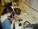
Test Rig
The following picture shows the prototype Car Computer test rig with prototype Motor Speed controller attached (no heatsink) and with burn marks from a problem !
