
Electronics Project
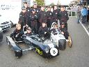
GpSpeed - Greenpower Speed Controller - Rotary Racer
![]()
Purpose
An electronic speed controller for Greenpower Electric cars. We have been using a, team built, motor speed controller in the Rotary Racer cars for a number of years. 3 different designs have been built and used. This is a new design that tries to bring all of our ideas together to produce a relatively simple, pupil buildable, speed controller which is flexible enough for Greenpower teams to use and extend to provide additional features.
The idea is to provide a platform and a kit allowing teams to get pupils involved in electronics rather than provide a fully featured and built end system. The basic speed controller can be extended with software and/or other hardware modules to provide a highly featured electronics control system for a Greenpower car. As well as speed control it offers battery voltage, current and other parameter monitoring. We don't provide a full, turn-key system, as we are trying to encourage the teams to involve the pupils in electronics and software engineering rather than just provide a simple to use with little understanding system and also allow teams to differentiate themselves from each other.
We provide an electronic schematic (circuit diagram) and PCB layout in Kicad format. This allows modifications by teams if desired. We also can supply manufactured PCB's allowing teams to easily build the design given here and complete kits with all components. Not all of the components are needed depending on the usage desired. By installing extra components and changing the on-board software the design can be extended to perform many different functions. We provide basic software that will operate the system. It is for teams to extend this system as wanted and to get involved in the electronics and software design.
So what can it do ?
- Can act as simple "soft start" device. Connected inline with the motor can simply provide a motor soft start on power on while using conventional switched relay systems.
- Can act as a simple "soft start" device with power switch. Using a simple on/off button will essentially behave as a "soft start" relay.
- Can act as a simple speed controller with throttle. A simple potentiometer either twist grip or other can be used to control the speed. Power limiting can be performed with an additional potentiometer to eek out those battery ampere/hours.
- Can measure battery voltage and current and display information to the driver and have driver buttons (via a separate display module).
- Can act as a PWM motor speed MOSFET output stage, battery voltage and current measurement device for a higher level computer control module (no processor installed).
Some Features:
- Uses mainly through hole components allowing easy assembly by pupils (year 7 upwards).
- Relatively low cost (Complete kit £77 + VAT).
- Uses screw terminals for the main wire connections, so easy to integrate by pupils.
- Has reliable high current PWM MOSFET output stage (160 Amps) with hardware and software current limiting. (proved over 5 years of GP racing).
- Filtered, efficient and reliable 12V and 5V supply for electronics from the main 24V battery supply. Used on board and available to external electronics.
- Has a simple PIC processor that can be programmed using Picaxe Basic or 'C' to do various tasks. Simple speed controller software and examples provided in Picaxe Basic and 'C'.
- Has onboard battery voltage and hall effect motor current measuring ability. This can be used for display to the driver or other purposes.
- Has 24V PWM fan driver with filter to control variable speed motor cooling fans (or other devices).
- Three external analogue or digital inputs: One for throttle/on/off and two free for use (temperature, car speed ?).
- Has I2C bus connection for driver display panel/controls with two digital IO lines. A simple LCD or LED display module (such as PicAxeAXE033) or own designed board to show the user voltage, current speed etc.
- Has limited memory for data logging. An I2C memory device could be connected to extend this, but there is no real time clock (Both could be added via Control connector, the PixAxe AXE033 LCD display has a RTC option as well that can be used). We now have a small data logging module available, see: GpSpeedDataLog.
- Has a serial port with power connector to allow a basic telemetry module to be attached. See info on telemetry at: GreenpowerElectronics
- Has connection to a separate car computer board for higher level control. This can be connected to RR's existing PIC based computer, to a new ARM based data logging computer module we are developing, an Ardino, a Beaglebone or to a Raspberry Pi etc. These will allow higher level control including data logging, telemetry etc etc.
- Can use it as a battery testing switch and datalogger to a PC. With a suitable load bank (multiple 50W bulbs or other resistive load) attached, the unit can perform a discharge cycle sending voltage/current info to a PC/laptop and then switch off the load automatically when down to 11Volts.
Info on our control/data logger project is at: gpControl
This is a simple, basic design plenty of scope for improvements :)
If you use this system all I ask is for you to involve the pupils as much as possible in the design, build, development and usage of the systems produced. Please get the pupils to build these, not provide a ready built one for them to use. The idea is to show, involve, educate and try to inspire young engineers.
Even better use this as a basis for ideas and develop your own system !
Note we do not provide any warranty that these systems will work or guarantee any support. The design and any kits are supplied on an “as is” basis.
We are, slowly, creating some Greenpower orientated electronics information at: GreenpowerElectronics
Status
- 2021-11-27: We have updated the GpSpeed design to 1.2. This increases the clearance on the ground and power plains to ease soldering and updates the design for the latest kicad software. Both the release Gerber files to make the PCB and the kicad design are provided.
- 2016-05-22: While investigating some issues with a schools GpSpeed controllers, it has come to my attention that there is an issue with the MOSFET insulating pads that some GpSpeed kits were shipped with. Please see: GpSpeedIssue1.pdf
- 2015-11-28: We are producing a data logging add on module for the GpSpeed controller. More information on this is at: GpSpeedDataLog We have added some initial information on using on data logging and telemetry at: GreenpowerElectronics
- 2015-11-28: 30 x GpSpeed controller kits have now been produced and are out with teams.
- 2014-11-15: Created a forum for help and information on the GpSpeed controller. This is at: /forum/GpSpeed
- 2014-10-19: The next 4 GpSpeed kist are being produced to send to schools. There will now be 20 GpSpeed controllers being built/in-use.
- 2014-10-01 RR had a number of first places this year and an overall 2nd in the Greenpower final. It is using the GpSpeed controller (plus other electronics).
- 2014-10-01 Survived reverse polarity connection at one school ! But please do make sure a 70amp fuse is always used inline with any batteries.
- 2014-07-26 The original GpSpeed demo software was setting the PWM frequency to 40 kHz not 20 kHz. Although this is not an issue the controller is probably more efficient running at 20 kHz. The GpSpeed example software has been updated to version 0v1 and now sets the PWM speed to 20 kHz. Thanks to Stephen Coughlan for noticing this.
- 2014-07-08 3 more GpSpeed kits sent to schools. There are now 14 GpSpeed controllers being built.
- 2014-06-27 GpSpeed-1.1 boards back and first kit sent off to a school.
- 2014-06-14 GpSpeed-1.1 board version finished and sent off for production. Minor board changes from feed back from schools helpers and pupils mainly to make it easier for pupils to build.
- 2014-06-14 Two more kits being made up for other schools. Total of 9 teams at 4 schools now making them.
- 2014-06-12 Crossley Heath school has design and made some nice 3D printed parts that improve the GpSpeed kit. See below for details.
- 2014-06-08 Tested in a GP race, worked fine.
- 2014-05-20 2 x PCB kits sent to some teams
- 2014-03-20 5 x Boards being made by various Chipping Sodbury teams.
- 2014-03-08 First unit installed into RR9 and tested at the Greenpower test day in Goodwood. After some fine tuning it worked !
- 2014-02-24 Board have been tested with motor test rig, all looks good. A number of simple test programs have been written by the pupils to test various features of the boards.
- 2014-02-17 PCB's have been assembled by the youngsters.
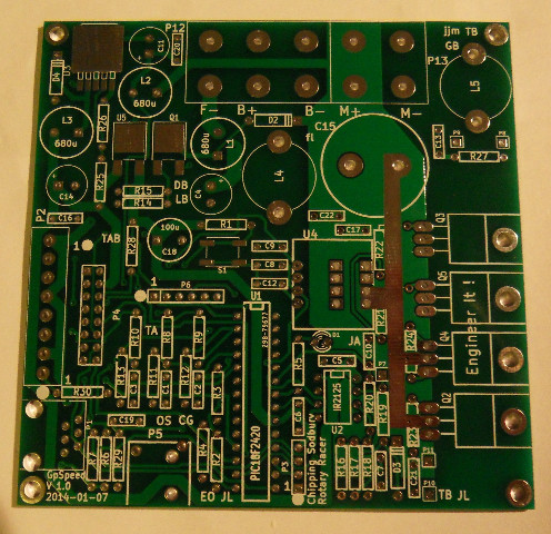
- 2014-01-22: PCB's are back from manufacture. Picture here
- A build diary is here
- 2014-01-08: PCB design sent for manufacture of prototypes.
- 2014-01-05: The GpSpeed board has been designed and its PCB is currently being tracked by the Rotary Racer and some from other CSS GP teams pupils. Should be available 24th of Jan 2014.
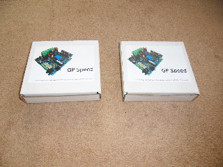
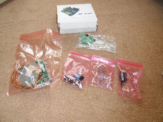
Kits
We used to provide a basic kit of parts to assembly these units, but we no longer do this. These were sold at cost price plus a small amount of money to the CSS teams whose pupils package up the kits (put all parts into bags)). These are supplied "as is" with no support, just to help teams get going. We hope some enterprising older pupils from schools may be able to help other teams who have problems.
 |  |
Pupil Involvement and Learning
There are various building and learning activities that pupils/students can do with the gpSpeed controller. Some of these include:
- Building the electronics PCB system and getting to know the component types used.
- Use of electronics tools including soldering irons, pliers, snips, screw drivers etc..
- Connecting modules together to see power electrics in operation.
- Usage of electronics test equipment such as multi-meters and oscilloscopes.
- Basic electronics mathematics
- Physics of the electronics circuits
- Electronics design.
- Power supplies and PWM circuits.
- Software programming for an embedded system.
- Instrumentation: making measurements and displaying them.
- Systems and Control systems.
** TBD ** Ideas for bits of work.
Specification
| Voltage | 12 to 24V DC |
| Motor PWM Current | Max 160 Amps, transient 640Amps |
| Motor Current Limit | Hardware 70 Amps approx (can be changed). Software controlled limit normally about 60 Amps but programmable |
| Soft start | Programmable. |
| Motor PWM Efficiency | At about 90 - 100% PWM, about 98% |
| Motor PWM Frequency | 20kHz (Programmable) |
| Fan PWM Current | Max 1Amp 24V, filtered PWM at 20 kHz (Programmable) |
| External Power supply | 12V at 500mA, 5V at 250 mA |
| Processor | PIC18F2520: Up to 32 MHz clock, 32 kBytes program FLASH, 1536 Bytes RAM, 256 Bytes EEPROM, 10 Bit 13 channel ADC, 2 CCP/PWM channels, SPI, I2C, UART, 4 timers |
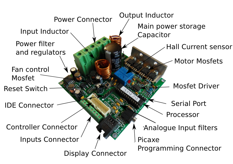
GpSpeed Block Diagram

This diagram shows the main operational blocks on the GpSpeed controller board.
GpSpeed Parts
Car Circuit Diagram Basic

This circuit diagram shows a complete circuit for a Greenpower Car using the gpSpeed controller. It is designed to be simple to use, no more difficult than using a relay, probably easier due to its use of screw terminals. The main batteries are on the left connected in series to provide 24 Volts. There are two main power switches, one SW2 in the -ve, ground connection accessible outside of the car and SW1 a current trip breaker accessible by the driver. Alternatively a 70 Amp fuse with switch could be installed in place of the breaker. It is ESSENTIAL to have a fuse or current trip breaker as near to the batteries as possible EVEN when testing on the bench. Batteries can generate a huge current that can be dangerous and damaging. It is also important to have a main power cut off switch close to the driver and easily used incase of speed controller or other electrical/electronic problems.
The GpSpeed controller is easily installed. It has screw terminals for the batteries B+ and B- lines and screw terminals for the Motors M+ and M- terminals. There are then three screw terminal connections for the, spring loaded, throttle potentiometer or hall effect throttle unit. Alternatively a simple push switch can be fitted to between two of the terminals.

This shows two possible throttle connections to the gpSpeed controller, a variable speed such as a twist grip and a simple on/off switch.
Documents
There is a version 1.0 and 1.1 of the GpSpeed. There are only minor differences.
| The user manual documenting the board for building, testing and usage. | gpSpeedManual-1.1.pdf, (Older design gpSpeedManual-1.0.pdf) |
| A more detailed development manual describing all of the pins and giving information of software development | gpSpeedDevelopment.pdf |
| The circuit schematic | gpSpeedSchematic-1.1.svg, gpSpeedSchematic-1.0.svg |
| The component list | gpSpeed-parts.ods, gpSpeed-parts.xls |
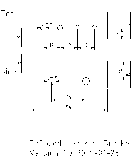
| Heatsink bracket design | gpSpeedBracket.dxf, gpSpeedBracket.png |
| A diary of the GpSpeed development | GpSeed Diary 3 GpSpeed Diary 5 |
| Some pictures of the boards during design and build | GpSpeed Picture |
| Some pictures from Crossley Heath schol. Note that they have produced some nice looking coil formers and large capacitor holder using a 3D printer. They intend to make the 3D designs for these available. | extra |
| Forum for help and information on the GpSpeed controller. | /forum/GpSpeed |
| GpSpeed 1.2 PCB production Gerber files | gpSpeed-1.2-production.zip |
| GpSpeed 1.2 Kicad design files | gpSpeed-1.2.zip |
PCB Layout
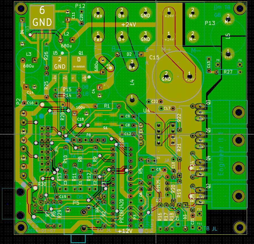
The two letter initials at various places on the board are from the Rotary Racer teams year 7 to year 11 pupils and Gareth (17) who did most of the PCB tracking for the board.
Components
See the documents list for the board components.
Other bits include:
| Twist grip throttle (about £40) | http://www.4qd.co.uk/accs/pots.html#mag |
| Twist grip throttle (about £9) | http://www.petrolscooter.co.uk/twist-throttle-grip-electric-scooter-es-05.html?fee=1&fep=2650&gclid=CInpn4zVirwCFdShtAodd3QAtg |
Purchase
We can supply complete kits or parts or just the PCB available with some awkward to buy bits to Greenpower teams. These are sold at cost price plus a small amount of money to the CSS Greenpower teams whose pupils package up the kits (put all parts into bags)). The aim is to help get pupils involved in electronics, software and systems and control.
| Part | Item | Price |
|---|---|---|
| gpspeed-pcb | PCB with PicAxe processor, inductor wire, PCB thickening wire, aluminum heat sink piece and MOSFET mounting pads, nuts and bolts | £22.70 + P&P + VAT |
| gpspeed-kit | PCB and complete pack of components to build the controller | £77.00 + P&P + VAT |
Note we do not provide any warranty that these systems will work or guarantee any support. The design and any kits are supplied on an “as is” basis.
Building
See the user manual in the documents list.
Mechanics
The board requires the main Motor control MOSFET's to be bolted to a heat-sink using insulating pads. We use a short length of 19x19mm angle aluminum 3mm thick to transfer the heat from the MOSFET's to a small heat-sink or car body part. The actual amount of heat energy to dissipate is fairly low: (below 4 Watts at full power). The board has 4 x 3mm holes, one in each corner for mounting. It can be mounted "open frame" to sal an aluminium sheet or in some form of box as long as a degree of ventilation is provided to the electronics or the box is thermally conductive to get the heat out. There is a 2D CAD file for this angle heat-sink in the documents section although your own designs can be used. Do make sure they are well debured and sanded smooth where the MOSFET's fit to save short circuits.
Stephen Coughlan who helps at Crossley Heath school has provided some nice 3D printed parts they have designed and made to improve some aspects of the GpSpeed. Information on these are at:
| Capacitor spacer | http://www.thingiverse.com/thing:355480 |
| Inductor Mount | http://www.thingiverse.com/thing:360545 |
Testing
See the user manual in the documents list for basic systems test. A small board with 24V or 12V power supply, and 12V 5W car bulbs can be used to test and experiment with the unit.
Software
The processor used is a PIC 28pin DIL device. A number of different PIC processors can be used. One that we recommend has 32 kbytes of program memory, 1 kbyte of RAM and various hardware peripherals. Two particular versions we would recommend include:
PICAXE-28X2
This comes preprogrammed to allow use in the PicAxe Basic programming environment. This system is commonly used by schools DT labs.
http://www.picaxe.com/Hardware/PICAXE-Chips/PICAXE-28X2-microcontroller/
PIC 18F2520
This is a bare PIC processor. It can be programmed in 'C' using a PIC programming device. Alternatively a serial boot loader can be flashed into the device allowing programming from a PC via a serial programming lead. Various 'C' based software programming environment can be used. We use the sdcc compiler and sometimes the pikdev environment on Linux PC's.
We provide the following code"get started" code. This includes the bare speed controller software ans snippets of code showing use of various features.
| Picaxe Basic simple speed controller. This allows speed control with switch or throttle and basic soft-start ability. | softwarePicaxe |
| Sdcc 'C' simple speed controller. This allows speed control with switch or throttle and basic soft-start ability. | softwareC |
DataSheets
| The PIC microcontroller | dataSheets/PIC18F2420.pdf |
| The Hall effect current sensor | dataSheets/hxs50-np.pdf |
| The MOSFET driver | dataSheets/ir2125.pdf |
| The MOSFET's | dataSheets/stp80nf10.pdf |
| The switch mode regulator | dataSheets/lm2575.pdf |
Extra Development
Some ideas for further development include:
- Measure and calculate the average the current used.
- Change the "soft start" ramp speed.
- Limit the power available to last the race possibly by use of a rotational potentiometer.
- Driver display module. This could use the PicAxe AXE033 LCD display module or other such I2C display modules connected to the Display I2C interface. Alternatively a custom display board could be produced. The GpSpeed display interface has two extra lines as well as the I2C bus to allow switches./LED's to be used. This can be used to display battery voltage/current, average current etc with suitable GpSpeed software.
- Speed input and measuring. A magnetic reed switch from a cycle computer can be used to input speed pulses. Suitable GpSpeed software can then measure the speed.
- Data Logging: Our GpSpeedDatalog module or a homebrew board can be used to provide data storage for a data log and a suitable real-time clock.
- Telemetry module can be connected to the serial port.
- Computer Control Module. For higher level control with data logging, telemetry etc a computer control module can be used. We are developing a simple ARM based data logging module that can be used with a custom data logging IO board for this purpose. Other control boards could be used through including Raspberry Pi's, Beaglebones etc.
- Modify to use a different processor.
- Improve efficiency of MSOFET output stage with active boost diode operation etc.
- Battery test rig discharge switch and data logger. Can switch on a bulb bank load and data log the voltage/current discharge profile of the batteries. It can automatically switch off when 11V per battery is reached to save battery damage during this testing.
- ...
Test and Play Rig
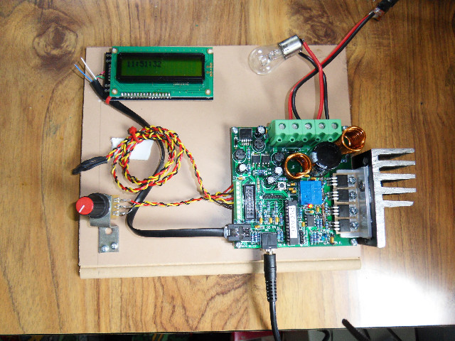
This is an example test rig. The GpSpeed is mounted to a small piece of MDF board (2.5mm holes drilled and plastic PCB pillars screwed in). A 10k ohm linear rotary potentiometer is connected to the throttle input and a TMP37 temperature sensor is connected to the secondary analogue input. A car 12V 20W stop light has been connected to the motor terminals and the power is supllied from a mains to 12V 48W "brick" type power supply. A fan can also be connected. A PicAxe AXE033 LCD display with real-time clock chip options is attached to the GpSpeed's display port.
With this arrangement quite a lot of experimentation and software development can be done in a safe and easy way. In the software area there is a suitable demo program available for this arrangement. It operates as a soft-start, current limited speed controller (the bulb will brighten and dim and fan go faster and slower with throttle position). It will also measure the temperature and read the real-time-clock. The throttle position, current being used, the time and temperature are displayed on the two line LCD.
Copyright
The design is copyrighted to the Chipping Sodbury Rotary Racer Greenpower team. It is provided free for non commercial educational uses.
Note we do not provide any warranty that these systems will work or guarantee any support. The design and any kits are supplied on an “as is” basis.