

Electronics Project - GpSpeedDataLog
Greenpower GpSpeed data logger
Purpose
This simple project adds data logging abilities to a GpSpeed motor speed controller. It is a small daughter board that plugs into the GpSpeed's P4 connector. It includes 512 kBytes (524288 Bytes) of non volatile EEPROM memory that the GpSpeed can use to store data samples. It also has a real-time clock chip with small rechargeable battery to allow the date and time to be kept and stored with the data samples. It is easily used from either Picaxe basic or 'C' software running on the GpSpeed.
The board is powered from the GpSpeed's 5V supply and communicates with the GpSpeed's CPU over a simple I2C serial bus. The design can be manually built using a prototype board such as Vero board or we can provide a small PCB for £5.00 including P&P and VAT (just PCB components need to be purchased by you(about £10 + VAT)).
For Greenpower use, it is useful to store samples of measured values like, Battery voltage, current, speed, throttle position etc. as the car travels around a track. The samples can be measured and stored at a suitable rate for the type of use. We would recommend between 1s and 10s as this provides a good compromise between enough data and storage requirements as well as allowing measurements to be averaged for enough time to give meaningful values. We recommend storing each value in binary to save space. Typically 16 bit or 8 bit sample values are useful scaled so as to give the best resolution available (fixed point). Given this a suitable set of data samples could have the following structure:
| Name | Size | Usage |
|---|---|---|
| Date | 24bits | Date: year, month, day |
| Time | 24bits | Time: hour,minute,second |
| Voltage | 16bits | The battery voltage scaled by 100. So 2410 is 24.10 Volts. |
| Current | 16bits | The motor current scaled by 100. So 16.50 is 15.50 Amps |
| Distance | 16bits | The distance traveled in 10's of metres |
| Speed | 16bits | The speed in km/hour scaled by 100. So 4860 is 48.6 km/hour. |
| Throttle | 8bits | The throttle position 0 to 100% |
| Temp | 8bits | The motors temperature in degrees. |
The total size of this sample "packet" would is 16 bytes. It makes things easier in software/hardware to use sizes that are a binary multiple.
Assuming a sample rate of 1 second the GpSpeedDataLog can store 524288 / 16 = 32768 sets of samples. This would be: 32768 / (60 * 60) = 9 hours worth.
For a typical Greenpower racing day you need storage for about: (Practice: 1.0 hours + race1: 1.5 hours + race2: 1.5 hours = 4 hours).
So the GpSpeedDataLog could store 32 byte sample packets at a rate of 1 second per packet to store all of the data for one days practice and racing.
If you also intend to use telemetry, it is worth calculating and adding some lap averaged data to the data packet. When using telemetry you are unlikely to get the data from all around the circuit. Perhaps you will only get it when the car is traveling close along the pit straight. If you calculate and store some critical parameters, such as the average current usage for a lap, then this will be provided in each telemetry packet. To average items over a lap you need to know when a lap is started/ended. We have used a GPS unit for this purpose, but instead a simple entry of the distance of a lap into the system can be used and the system can calculate the averape every time that disptance is passed. The unit would bee to be able to measure distance tranvvelled using a suitable cycle read relay or similar for this.
Circuit Diagram

Circuit Description
This circuit uses four 1MBit (128 kByte) I2C EEPROM chips (U1, U2, U3 and U4) to store the data samples. The are connected to the I2C communications bus so the GpSpeed computer can read and write data to them. Between the 4 EEPROM chips they can store up to 512 kBytes of data accessible on a per Byte basis.
There is also a DS1307 or equivalent real time clock chip that keeps a track of the date and time to the nearest second. It has a small rechargeable battery, BT1 that allows it to maintain the date/time even when the system is powered off. This battery is charged through the diode D1 and resistor R1. D1 make sure the battery does not discharge when the power is off and R1 limits the charge current to the battery. The crystal X1 runs at 32768 Hz (a convenient binary multiple of 1 second) and is used as the accurate time clock source. The DS1307 is connected to the I2C serial bus so that the GpSpeed's CPU can read and set the date/time.
The power for the board is provided from the GpSpeed's 5V line. It has 4 capacitors spread amongst the chips on the board to provide power for current spikes and thus smooth the power supply voltage level preventing glitches to the boards operation.
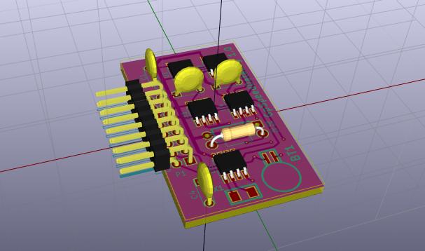
PCB Layout

Components
The components used are:
| Qty | Parts | Type | Value | Supplier | PartNumber |
|---|---|---|---|---|---|
| 4 | U1,U2,U3,U4 | IC | M24M01-RMN6P | Farnell | 1670817 |
| 1 | U5 | IC | BQ32000DR | Farnell | 1754773 |
| 1 | BT1 | Battery | MS621fe | Farnell | 1614634 |
| 1 | X1 | Crystal | ABS07-32.768KHZ-T | Farnell | 2101347 |
| 1 | C1 | Capacitor | 1uF | Farnell | 2112910 |
| 3 | C2,C3,C4 | Capacitor | 100nF | Farnell | 2112751 |
| 1 | D1 | Diode | 1N4148 | Farnell | 9565124 |
| 1 | R1 | Resistor | 1k2 | Farnell | 9341226 |
| 1 | P1 | Connector | SSW-108-02-G-D-RA | Farnell | 1668366 |
| 1 | PCB | Pcb |
Note this component list is for the PCB based design and uses surface mount components for the IC's and crystal. For a Vero board based design through hole versions of these components would be required. For the IC's 8 pin, PDIP packages are available.
Building
A temperature controlled soldering iron (soldering station) is best as this will reduce the likely hood of damage to the PCB while soldering. Non temperature controlled ones can heat the board to a temperature that damages the adhesive holding the copper tracks to the PCB. Something like the following are fine:
Farnell:TENMA 21-10115, 2064549, £37
RS: RS AT60D, Soldering Station, 220V ac 60W, 799-8939, £66
Maplin 60W Mains LCD Solder Station, Code: A55KJ, £40
Have a look at: http://www.pcb-soldering.co.uk/
The tools needed are:
-
Soldering iron with a fine tip. Ideally electronics temperature controlled type, this will reduce the likely hood of damage to the PCB.
-
Solder. Thin-ish multi-core solder. Solder paste is also an option.
-
A “solder sucker” is useful when the soldering goes wrong !
-
A length of “solder wick” is likely to be useful to remove excess solder.
-
Small side cutters.
-
Small pliers.
-
A “helping hand” and/or PCB support tool can be useful to hold the board while soldering.
-
A multi-meter to test the board.
This lists a rough order in which to assemble the components onto the PCB. See the information in the GpSpeed manual and elsewhere on the Internet on soldering techniques. The design uses some relatively small surface mount devices to add a bit of difficulty! A fine tip soldering iron, thin solder and small tweezers as well as young eyesight is useful :) Some schools have used solder paster rather than solder and have siad this was easier for them.
- First solder the IC's: U1 through U5 onto the board. To do this place each one individualy on the board the correct way around. Pin1 of the IC has a silk screen line next to it on the PCB. For IC U5 there is a small white dot on the chip near pin 1, for U1-U4 the manufacturers logo, ST, is near pin 1. In all cases if the chips text is the correct "readable" way up pin 1 is at the bottom left. Then apply a clean (wipe on a damp sponge) and small soldering iron tip to the pad next to the pin, wait a few second for the PCB and IC leg to heat up, apply a very small amount of solder and then remove the iron. It is worth using tweezers to hold the chip in place while soldering. A good practice of two handed work! If the IC has moved, apply the soldering iron again to melt the solder and with your other hand move the chip using a cocktail stick, small jewelers screwdriver or small tweezers. Once in place solder the rest of the pins. If you over solder use some solder braid after soldering all of the pins to remove the excess solder.
- Place and solder the crystal X1 in place as per the IC's
- Place and solder the through hole resistors, capacitors and diodes chopping off the excess leg wire with side cutters. Note the direction of the diode.
- Solder the connector P1 in place.
- Finally solder the small battery in place. Make sure you do not short the pins while soldering this and do not apply the heat for too long as the heat can cause the battery to pop open (make sure you use protective eye goggles). It is worth using a small blob of glue under the batteries body to hold it in place. Evostick would do.
Some soldering guides
- https://www.sparkfun.com/tutorials/category/2
- http://www.instructables.com/id/How-to-Solder-SMD-ICs-the-easy-way/
- http://www.infidigm.net/articles/solder/
Testing
Check that the 5V power line is not shorted by using a DVM set to ohms to measure the resistance between ground (One of the connectors odd numbered pins, and the anode of D1 (or across any of the capacitors). This should be higher that 500 Ohms.
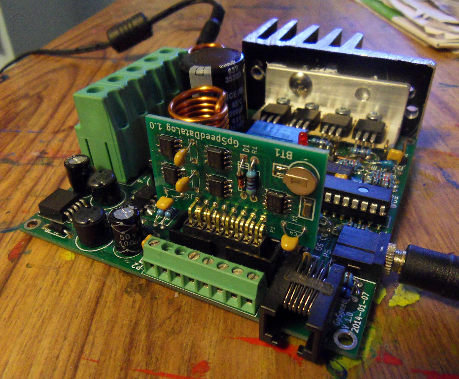
The board can then be plugged into the GpSpeed controller's P4 connector. Pin 1 of both connectors should line up. It is difficult to put the board in the wrong way round as the PCB will hit components on the GpSpeed board.
There is a simple GpSpeed Picaxe test program named: gpspeed-test-datalog.bas that will perform a simple test of the board and provide a basic demonstration of its usage with Picaxe Basic.
Datasheets
Datasheets for the IC's used are at:
Software
This provides some basic information on how to access and use the board from Picaxe Basic. It can obviously also be accessed when using the 'C' programming language if you are using this on a GpSpeed controller board.
See the Pixaxe manuals for how to access I2C devices and especially I2C EEPROM's and theBQ32000DR (like a DS1307) RTC chip.
We have provided a simple borad test program: gpspeed-test-datalog.bas which tests the board and shows basic access to the on-board chips and a demo program: gpspeed-demo-datalog.bas that gives an idea on how to use the board for data logging on a GpSpeed controller. These are in the GpSpeed software directory ../GpSpeed/softwarePicaxe
Some general pointers:
- There are 4 separate I2C EEPROM memory devices each containing 128 kbytes of memory.
- Each EEPROM has two separate I2C addresses on the I2C bus one for each 64k Byte bank of memory. Addresses using 8 bit format are: U1: [0xA0, 0xA2], U2: [0xA4, 0xA6], U3: [0xA8, 0xAA], U4: [0xAC, 0xAE].
- Each of the 64k Bytes of memory within each bank of the memory chips is addressed by sending the address as a 16 bit value.
- When writing data to the EEPROM it takes a maximum of 5 ms to write the data. You must make sure you do not write any other data for 5 ms after a previous write.
- You need to initialise the RTC (real time clock) chip with a suitable starting date and time before using it. It will then maintain the time using the on-board rechargeable battery as a power source. It will charge this battery when powered normally, it takes about 3 hours to fully charge.
- There are a set of Picaxe example software routines in the examples for memory and RTC access.
- Note, when the picaxe serial cable is used as a serial debug port for inputing typed data from the user as it is in this program, then the picaxe cannot be programmed once the program has started. To program it in this case: Start the programming and then press the GpSpeed reset button. There is a small window of opportunity when the picaxe starts up were it can be programmed in this case.
Usage
Once you have the data logger working and some simple low level software code to access it, you can now add this to the main GpSpeed running program. The functions you will want to provide are:
- Setting up the RTC to the correct time and day. This will likely only have to be done once in a while, perhaps once per year to make sure the time is in sync. You could use a custom Picaxe program to do this or add some ability for the main GpSpeed controller program to set this up in response to display button presses or via the serial port from a PC or Laptop.
- Measure and storing the sampled values. The current GpSpeed demo code measures a few parameters. These can be stored into the data logs EEPROM over the I2C bus.
- Some ability to read the data log back into a PC. This is easiest to do via the Picaxe programming/debug serial port although the GpSpeeds second serial port could be use as well. The second serial port could be connected to a wireless device such as an XBee for wireless download of the data log. It will probably be convenient for the GpSpeed's software to output the data logs sample data in a human readable, ASCII encoded text format such as CSV (comma separate values). Each line in such data would have the sample values written in ASCII text each separated by a comma. Each 1 second set of samples would be store on a new line. See the example below.
- Note if you are using a Picaxe AXE033 display module with the GpSpeed the RTC clock chip on this device should be removed as it will interfere with the one on the GpSpeedDataLog board.
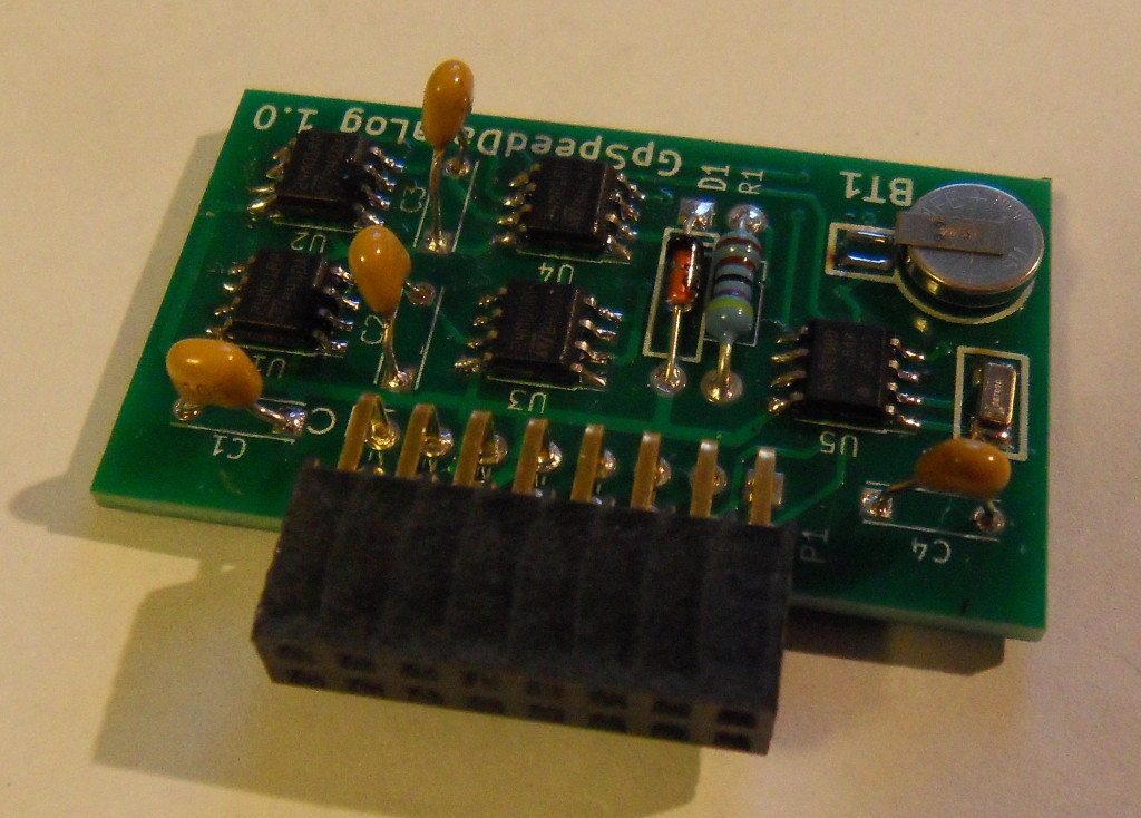
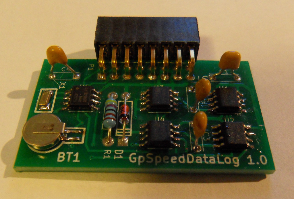
Pictures
 |
 |
 |