
Driver Display
Having a driver display can be useful in a Greenpower car to help inform the driver what is going on. This could take the form of a few simple LED's, simple LCD/LED text displays to full graphic touch screens. It is important that the display does not take the drivers attention significantly away from the actual driving however for safety.
Some of the uses include:
- Display motor current.
- Display average motor current.for the last lap.
- Display battery voltage.
- Display battery energy remaining.
- Display speed.
- Display motor temperature.
The main use would be to allow the team/driver to manage overal power usage
Unfortunately Greenpower have banned sending data to the car, so messages from the pits, such as "pit next lap" are not allowed.
Display Types
- LED's: Having a few LED's is the most simple display. These can light up perhaps to show if too much power or too little power is being used. Simple bar graphs are also possible to show, for example, the battery voltage. They are easily driven from a small microprocessor and don't take too much power.
- Simple LCD/LED character displays: These can display from 1 to 4 lines of text each, perhaps, 16 characters long. Some require quite a few microprocessor lines to drive the LCD/LED's directly, but some have an onboard controller that provides a simple serial or I2C interface that uses one or two microprocessor lines. They are relatively easy to program for and don't take too much power. Note that the pure reflective LCDs work well in bright sunshine, whereas the LED or OLED displays need to be shaded so that they can be seen well in bright sunshine (although they do look cool!).
- Graphic display panels, perhaps with touch operation as per mobile phones can also be used. These are more difficult to use but do have a wow factor. These displays often use a complex and fast digital interface that can only be driven by fast processors with appropriate hardware interfaces. There are some available that use an onboard microprocessor controller to interface to the display and present a simpler SPI, I2C or USB interface to the outside world. They do use more power that other display types.
A simple LED display or LCD/LED character display can be used with simple microcontroller chips and boards such as Picaxe, PIC, Ardino etc. Although it is possible to use some "intelligent" graphic display panels with a small microcontroller, these are more suitable with larger more powerful computers such as Beaglebone's or Raspberry Pi's.
Interface Types
- LED: A single LED can often be driven directly from a microprocessors output pin via a current limiting resistor. A LED normally has about a 2V voltage drop and produces a reasonably bright light with 10mA of current flowing. So with a 5V microprocessor a suitable resistor value would be: (5 - 2) / 10e-3 = ~330 Ohms. For greater brightness a higher power LED can be used with a greater current. Note however that the microcontroller's pin may not be able to supply this current and a transistor buffer may need to be used.
- LCD/LED text display direct: This requires a number of microprocessor output pings to drive the rows and columns of the individual LCD/LED segments.
- LCD/LED text display I2C/serial: This requires one or two microprocessor IO lines plus ground. The serial interface is the simplest with the microprocessor sending a stream of bits making up individual 8 bit bytes as commands and data. The displays datasheet/manual will describe the commands available and how to write characters and digits to the display. The I2C interface is similar, but has the benefit to being a bus that allows multiple devices to be connected to the same two lines. Each device has an address, otherwise the communications is similar to the simple serial case.
- Graphic display interface direct: These normally require at least 16 lines for pixel data along with clock, vertical sync and horizontal sync lines that operate at high speed. A dedicated display controller is normally needed to drive this.
- Graphic display interface intelligent: Some displays come with an onboard microcontroller that interfaces to the graphic display and provides a simpler USB, SPI or I2C interface to drive. Note however that if driving a graphics display it is likely that the controlling processor will need a lot of RAM memory to create the "images" to be displayed. This is normally beyond the reach of a simple microcontroller.
Connecting a display to the GpSpeed Controller
The GpSpeed controller uses a simple 8bit microcontroller. This sections shows how to connect and use a LCD/LED display with such a controller.
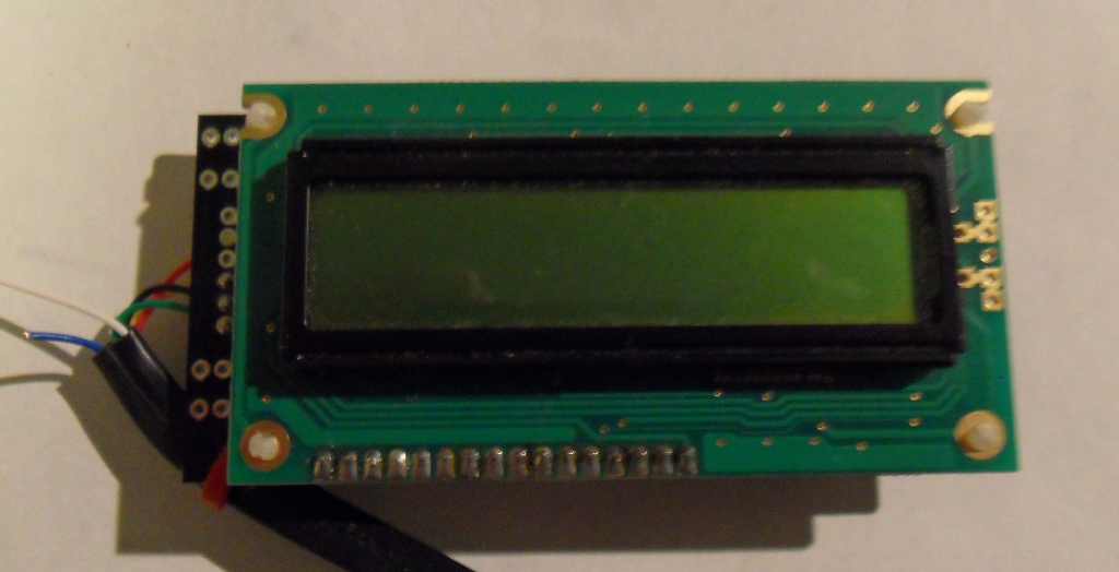
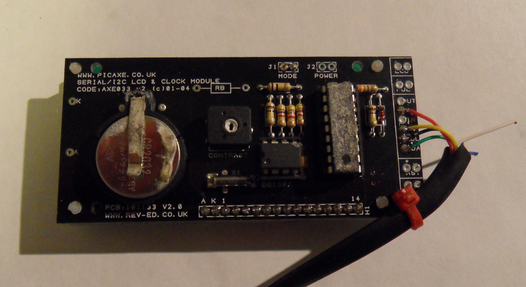
The GpSpeed controller has a connector that is designed to be used to connect to a driver display. This RJ12 type of connector provides a simple 6 wire interface. This provides 5V power, an I2C serial bus for communications and two spare lines for other uses such as switches or LED's. It can easily be used with the Picaxe AXE033 module:
Module: http://www.picaxe.com/Hardware/Add-on-Modules/Serial-LCD-Module/
Datasheet: http://www.picaxe.com/docs/axe033.pdf
The display can be used to display various information from the GpSpeed controller. Some examples are:
- Motor current. The instantaneous motor current.
- Average motor current over a period of time, ideally the last lap.
- Battery voltage
- Speed
- Motor temperature
- Throttle position
The Picaxe AXE033 module comes as a simple kit to build. It also offers the ability to install a real-time clock chip and battery to maintain the date and time for data logging or other purposes.
When making the AXE033 module note the following:
1. The J1 link needs to be installed for I2C mode.
2. The link J1 should be left open.
3. Make sure you solder the LCD PCB to the controller PCB the right way around !
To wire the LCD module to the GpSpeed an RJ12 telephone type of lead can be used. (RS: 446-664).
The GpSpeed connector information for display connector p1 gives the pinout and the colours of the wires in a typical RJ12 lead.
Some Notes:
- Try and keep the cable as short as possible.
- Run the cable away from battery and motor power cables and any others that could cause interference.
- Note that the displays control variable resistor may need to be adjusted in order to actually see the display.
- It is worth adding 2k2 pull-up resistors from the I2cClk and I2cDat lines to the 5V power line at the display end of the cable to reduce the effects of noise.
- The display can be written to using normal Picaxe AXE033 I2C commands. See the AXE033 datasheet and the GpSpeed demo programs gpspeed-test-display.bas and gpspeed-demo-0v1.bas for more information.
For more information see the GpSpeedDevelopment document at: http://www.greenpower.beamweb.co.uk/groups/electronics/GpSpeed/index.html