

Motor Speed Controllers
![]()
Reasons
It is perfectly possible to use a simple switched high current relay to switch the motor on and off in a Greenpower car. This is simple but has some disadvantages:
- Switches the motor on hard causing drive snatch and possible damage.
- Switches on hard taking a large current (> 120 Amps) from the battery. This can cause battery damange over time and stress the electrical system including blowing current protection trips at race start.
- Relay contacts can wear out with the heavy switching.
- High current relays can take quite a high current to operate and even may not be as efficient as a very high efficiency speed controller. One solenoid we used to use took 1.6 Watts of energy just to operate!
- Just on and off so difficult to drive the car slowly and control the power output.
- There a great opportunity being missed to show electronic engineering to the students !
One of the core things to get right in the Greenpower challenge is to manage the use of the batteries energy so that the car can last the race, just. To much average energy usage and you will stop on the track near the end watching all of the other cars go past and damaging your batteries in the process, Too little average energy usage and you could have gone faster/further in the race. Its a fine line and so managing the average energy usage is important. This can be done with variable ratio gears, but often the step in radio is to great for good control. Variable ratio gear systems sound ideal, but their efficiency can be very low. Another way is to use gears to get close and then use an electronic speed controller to tweak the motors energy output up and down a little.
How It Works
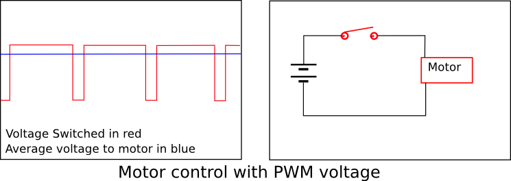
Electronic Motor Speed controllers normally use a pulse width modulation (PWM) technique. This is very simple, they just turn the motor on for a time then off. The ratio of the on time to off time determines the average power. To make this seem-less controllers normally switch on/off at about 20,000 times a second or so.
In order to switch on and off quickly and efficiently electronic switches are used. Commonly Metal Oxide Semiconducting Field Effect Transistors (MOSFET's) are used. These small devices are capable of switching 100's of amperes of electrical current on and off within nano seconds (ns 1e-9 seconds) with just a small voltage changed on its controlling terminal called the gate.
The duty cycle (ratio of on to off time) is normally controllable using a twist grip throttle. Normally a soft start technique is used. All this does is slow the change from 0% duty cycle up to 100% duty cycle so it takes a few seconds to get to full power.
How to
You can either purchase a suitable controller, build our GpSpeed controller kit or design and make your own speed controller. If you have someone with electronics experience and can work with the pupils building you own with heavy pupil involvement is an excellent way to involve them in electronics engineering and programming.
Installing a speed controller is relatively straight forward. They normally need the 24V DC -ve and +ve supplies from the battery taken to then on relative thick leads (10mm^2 is good but > 6mm^2 is ok). The motor is connected to them using similar leads. On the GpSeed controller the re is a screw terminal block so that it is easy to attach wires directly. Some speed controllers use spade terminals that need to be crimped to the wire.
The following diagram shows a possible full Greenpower cars electrical system with a speed controller installed.

As well as the power input and output wires most speed controllers have some control wires that allow control of the duty cycle and hence overall power output. These can be connected to a simple on/off switch or to a variable speed twist grip.
There are two general forms of throttle control: 2 wire and 3 wire.
- A three wire control normally provides a +ve and -ve voltage source (normally 5 Volts) and expects a variable voltage between these voltage extremes applied to the control wire. A simple 3 terminal potentiometer can achieve this. Most speed controllers expect around a 10 kOhms potentiometer and a 0V to 5V control range.
- There are now quite a few Hall effect twist grips on the market. These normally require a 5V power source and provide 1V to 4V on there output terminals. Quite a few speed 3 terminal controlled controllers are compatible with this, but they may need configuring so that the reduced 1 to 4 volt range covers the off to full speed range.
- Instead of a variable resistor a switch and resistor can be used for a simple on/off control with soft start.
- Some speed controllers only offer 2 wire control. A variable resistor or switch can be used with these but probably not a hall effect twist grip.
See your controllers datasheet or user manual for how to do this.
Some controllers, such as the GpSpeed, can also be controlled by digital commands from a micro controller (computer) unit.
Control Options
One of the reasons for using a speed controller in a Greenpower car is to control the average energy used so you can use all of the power available to go as far and fast as possible in a race. There is a separate section on this. PowerControl.
Pupil Work
There are quite a few areas of work that the pupils can be involved in. Some of these include:
- If a speed controller kit is used the pupils can build this. They will see electronic components and learn what they are and how to handle them. Learn soldering and mechanical assembly of smallish items.
- Be able to perform electrical wiring work cutting wire, stripping insulation and using screw terminals and crimp terminals.
- Be able to start to understand electrical and electronic schematic diagrams.
- Be able to see testing in action and probably fault handling !
- Use it for real in a race and see the benefits of the better control.
Some of the more gifted pupils will be able to design and build their own speed controllers, certainly quite a few have accomplished this at about sixth form age.
Specification
In order to be of use in the Greenpower challenge the speed controller has to have certain capabilities. The main ones of these include:
| Voltage | 24V or greater |
| Maximum current | Peak of 130 Amps (stalled motor) or restricted to a minimum of 60 Amps.. |
| Current control | Some controllers offer a soft start and current limiting function. These are preferred as they reduce load and damage to the batteries and motor. |
Parts
| GpSpeed | This is an electronic speed controller kit designed by the Rotary Racer team for their cars and made available to any Greenpower team. It is a highly efficient and pretty robust controller with a lot of features providing much more that just electronics speed control |
| 4QD | 4QD produce a range of ready made controllers. These have been extensively used in the Greenpoer series over many years. A popular one is the Pro 120 24. |
| Scooter | There are quite a few cheap Chinese produced speed controllers for scooters available. Some of these will be suitable, but make sure there current handling abilities are high enough. |
More Information
| GpSpeed Controller | There is more information on the GpSpeed controller which might help understanding in this area |
| http://en.wikipedia.org/wiki/Electronic_speed_control | Wikipedia information on speed control. |
| http://en.wikipedia.org/wiki/Pulse-width_modulation | PWM info |