

Voltage Transients in a Greenpower car
Introduction
The following is a basic simulation of a Greenpower electrics circuit using a relay. It shows the transient voltages that can occur on the wiring of a Greenpower car and shows some methods that can be used to reduce these and eliminate the issues. As with all simulations it may not be completely correct, but the basics are correct.
Basic Circuit
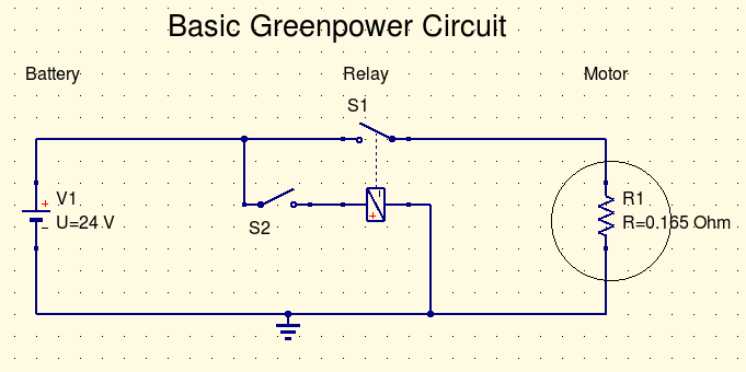
This is a basic Greenpower motor power circuit with a simple on/off relay. However there is really a bit more going on in this circuit that this simple circuit diagram shows. Wires are not simple 0 Ohm resistance connections. batteries are not solid 24V DC power supplies and motors certainly aren't a simple resistive load.
So we can expand this circuit diagram to introduce a more detailed representation of the circuit which will allow us to simulate it on a computer and see what the likely voltages and currents are.
In electrics/electronics there are 3 basic component attributes:
- Resistance: There resistance to the flow of electrons. Takes some of the energy of movement and turns this into heat disapating some of the energy. http://en.wikipedia.org/wiki/Resistor
- Capacitance: A capactor "stores" electrons: http://en.wikipedia.org/wiki/Capacitance
- Inductance: An inductance tends to keep electrons moving acting like an inertia. It does this through magnetic fields generated by the passing electrons. http://en.wikipedia.org/wiki/Inductance
Most components, and that includes wires, have various values of these attributes. Wires for example have a resistance to the flow of electrons, although this is quite low. They also have an inductance which depends on length and if it is coiled etc. The wires insulation, although highly resistive, does allow a degree of electrons to flow through it. And there is a capacitance between the wire to its suroundings. In the simple case of a static, unchanging flow of current the inductance and capacitance have no effect, but when the flow of electrons is changed rapdly their effect is large and needs to be taken into account.
Simulation
![]()
- Qucs Circuit File: Transients.sch
Description
This is a simple, but more detailed, simulation of a Greenpower cars electrical system when a relay is used. There is the battery to the left. This provides 24 Volts and has an internal resistance of about 0.004 Ohms. The example assumes a wire of 5mm diameter and 2m in length (2 x 1m). This will have an inductance of about 2.7uH. R3,C1 are there to simulate insulation/general resistance and capacitance. For simplicity the two battery wires are simulated with an inductance/resistance on just the one wire although in reality both wires would have this (half the amount on each wire).
The motor is simulated as a resistor in series with an inductance (from the copper wire windings), these are the values from Fracmo. There is also a 1uF supression capacitor, depending on how the motor is wirred this could be 2uF if the relay switches the +ve terminal rather than the -ve terminal. Note that the Fracmo motor has a 1uF capacitor between the +ve and -ve input wires and a 1uF capacitor from the +ve wire to the case. The case of the Fracmo motor should ALWAYS be grounded/connected to the -ve. As the case is often connected to the chasis, the chaisis should be connected to the battery -ve terminal. If this is not done large transient volatges can appear on the chassis ...
The relay is switched on after 1ms in time and then switched of at 2ms with a motor that is not spinning. The first graph shows the voltage (Pr1) just before the relay and the second the voltage (Pr2) across the motor. You can see with this arrangement and component values there is a voltage transient of many thousands of volts ... This is easily enough to destroy sensitive electronic equipment.
(Note that the actual waveform dipicted here is not really correct. The ringing frequency is really much higher, and starts in the +ve direction, but the resolution of the simulation is unable to capture that and the data is "aliased". However it shows the basic effect better :) See later how to change the simulation to simulate and display the ringing in more detail.)
Where does this come from ? The inductance of the wiring from the battery to the relay. When the motor is switched on a huge current of electrons starts to flow. This builds up to around 130 Amps worth that is 8.12 x 10e20 or 812,000,000,000,000,000,000 electrons per second. (Electrical engineers have a lot or marbles at their command :) ). When this is switched off by the relay the effect of the inductance is to try and keep these electrons moving (like mass inertia). So the electrons keep on going from the relays terminal but there is no source so the number of electons diminsh quickly and they start building up on the other side of the inductor. Some leak through the insulation resistance and some charge the insulations capacitance (overall capacitance of the circuit near the relay terminal). The insulations capacitance in concert with the inductance resonates a bit like a guitar string and so those 8.12 x 10e20 electrons start flying backwards and forwards causing the +ve and -ve voltage swiings in a decaying sine wave type fashion.
There is also a transient across the motor, so you will have to be careful if you connect sensitive electronics across this.
If the motor is aready spinning (push start) the efective motors resistance is higher, the motor current is lower and the transient will be less. Give the car a good push off !
How to Improve
If you wish to run sensitive electronic circuits from the main batteries you will need to make sure that the transient voltage spikes are reduced to levels that the devices power input can cope with. There are a few techniques:
- The transient is casued by the inductance of the battery connection wire. If it is possible run separate wires to both of the battery terminals to power the electronics. The battery is like a huge capacitor with low series resistance. There will be little voltage spikes here. This can be difficult with a GP car if connectors are used. However keeping the connectors close to the battery and wiring the electronics from there would reduce the voltage spikes.
- Putting a reasonably large value capacitor and low value resistance from the relay terminal to the negative terminal or across the relay terminals. This can be in series or parallel configuration. This is often called a snubber circuit. The capacitor will carry the current for a short time when the relay opens. The resistor restrics the electron flow turning this energy into heat and so damps out the "ringing" of the inductor capacitor combination.
- As well as doing the above include a transient spike filter on the power lines to the electronics. This can be implemented with an inductor/capacitor or resister/capacitor filter depending on the level of current you need for the electronic circuits. A transient suppressor component can also be used here.
Possible components
| Component | Part |
|---|---|
| C1 snubber, 1uF > 100V DC | RS 115-152 |
| R6 snubber 10Ohms 0.5Watt | RS 707-8063 |
| L3 380uH inductor | RS 233-5285 |
| C3 220uF capacitor (larger than the 100uF capacitor in simulation, provides better supression) | RS 365-4379 |
Design with Suppression
![]()
- Qucs Circuit File: TransientsFixed.sch
This shows a circuit with the transients supressed. C1 (1uF) and R6 (10 Ohm) form a snubber circuit across the input power. They are placed close to the relay terminals between the positive and negative close.
The diagram shows two separate electonics pickup points, both with an LC filter. The Pr3.Vt is taken close to the snubber circuit ans shows a modest 1V transient. The Pr4.Vt volatge is taken close to the batteries and shows only a very small transient. If the current draw is low a simple RC filter can be used, but that R will dissapate a bit of power. A transient supressor can also be placed in parallel with the capacitor. The electronics circuits would be connected where Pr3 or Pr4 is.
Alternatively the snubber can be placed across the relay terminals as show below. This will often bea easier as the relay terminals are located close to each other.
![]()
Qucs Circuit File: TransientsFixed1.sch
This will reduce the transients on either side of the relay. The transients across the electronics take off point would be higher though.
Speed Controllers
Generally there is much less of an issue when a PWM electronic speed controller is used. Normally these devices have a large inbuilt stoarge capacitor across the power input lines. So although the PWM controller is switching on and off the power to the motor like a relay (although at a quicker rate ~ 20kHz), the capacitor sources/sinks the surge currents and the battery supply wires don't have transients on them. However, there can be a surge when the main power switch is switched on with the large current charging up the capacitor in the PWM unit. This could cause a transient volatge on the wires. This can occur especially near the on/off switch (it may arc as well). So conneting the electronics supply separately to the battery terminals or close to the PWM unit can help. The LC transient spike filter, as described above, should also be used on the power lines to the electronics to smooth out any transients present.
About Simulations
The above electronic circuit simulations have been performed using the QUCS circuit simulator. This is OpenSource free software and is described on the main electronics page here. The circuit diagram files can be downloaded from the links above to try them out.
The simualtions solve differential equations describing the components and circuit interconnections. With a transient simulation the values of all nodes are calculated many times over the time of the simulations to build up an array of results that are plotted in the graphs.
The first simulation does take a bit of time to run due to how the maths is working in that example. The frequency of the transients is greater that the resolution of the simulation and so the differential equation solver has a problem converging an a result. Because of the resolution of the output data the graph actually showing an incorrect frequency of ringing (data aliasing). If you modify the transient analysises start and end times to 1.9ms and 2.1ms respectively, narrowing down on the point the relay is opened, you will see the higher frequency ringing correctly. There is always a danger in using mathmatical simulations !